Swegon LOCUS a Instructions For Use Manual Download Page 5

5

22/12/2022                    Swegon reserves the right to alter specifications.
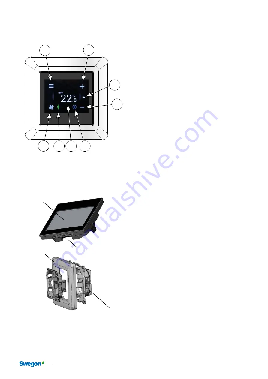
LOCUS

User mode

A. menu
B. increase
C. 

swipe left to go to the next page

D. decrease
E. 

symbol showing cooling or heating in progress

F. 

shows programmed setpoint or measured temperature

G. 

shows occupancy in the room

H. 

press to activate boost flow 

A

B

C

D

E

F

G

H

Micro SD card reader

RU display

Frame

Mounting attachment

Component parts

Summary of Contents for LOCUS a

Page 1: ... with applicable EU directives Symbols in this user manual Warning Caution Contents Key to symbols 1 Application area 2 General 2 Protective equipment 2 Electrical safety 2 Handling 2 Installation 2 Assembly 3 Dimensions 3 Connection 4 Modbus 4 Commissioning 4 User mode 5 Component parts 5 Technical data 9 Connection 9 Standards and directives 9 ...

Page 2: ...ling installation cleaning and service maintenance Electrical safety Permitted voltage see Electrical data It is not permissible to insert foreign objects into the product s connectors or the electronics ventilation openings risk for short circuiting Cable classification Always follow the local national rules for who are permitted to carry out this type of electrical installation Handling The prod...

Page 3: ...s Schneider Exxact Merten Gira Elko etc The installation position needs to be selected with care to eliminate fault factors that can affect the measurement For example the room unit should not be exposed to direct sunlight distance from the user air flows from windows and doors air flows from ventilation nozzles air flows through the junction box draughts caused by an external wall Figure 1 Recomm...

Page 4: ...it s Data bits 8 Parity none Stop bits 1 Configuration can be performed via the LOCUS panel by going to the Parameters menu There you can access all Modbus settings for the URC controller 1 2 3 4 5 6 7 8 9 10 11 12 13 14 15 16 17 18 19 20 21 2 2 2 3 2 4 2 5 Figure 5 Controller URC1 Figure 4 Room unit LOCUS Commissioning Note Check all settings and parameters during commissioning In this way you ca...

Page 5: ... C swipe left to go to the next page D decrease E symbol showing cooling or heating in progress F shows programmed setpoint or measured temperature G shows occupancy in the room H press to activate boost flow A B C D E F G H Micro SD card reader RU display Frame Mounting attachment Component parts ...

Page 6: ...isplay Main screen active The and signs increase decrease the setpoint temperature Boost mode enabled Swipe left for display mode two Show input values from connected sensors Swipe right for display main screen Main menu Settings menu Code 1919 Main menu Display settings Backlight Brightness in display Main screen boost Make boost button available Main screen alarms Show alarms symbol ...

Page 7: ...nal temp sensor Main screen value What to show on main screen Stand by screen What to show on stand by screen Modbus settings Modbus settings For communication with controller unit Modbus ID ID for LOCUS unit 247 Stop bits No of stop bits 1 Parity Choose parity None Data bits No of data bits 8 Baud rate Communication speed 38400 ...

Page 8: ...o alter specifications 22 12 2022 Parameter Parameters Modbus list Parameter menu Choose Modbus register Main menu Thermostat settings Use of temperature sensors Temp Calibration Offset of measured value Main menu Information SW version ...

Page 9: ...LOCUS Connection Description VDD RJ12 12 40 VDC power supply A RJ12 RS 485 bus connection B RJ12 RS 485 bus connection GND RJ12 Earth for 12 40 VDC power supply Memory card slot The user panel s software can be updated via a Micro SD card Display Capacitive touch TFT Display QVGA 2 3 Screen resolution 320 x 240 Communication Modbus RTU via RS 485 Temperature sensor Internal 10K NTC sensor Operatin...

Reviews: