Swegon IQlogic+ Function Manual Download Page 13

GB.BlueBox.180415

Swegon reserves the right to alter specifications.

www.swegon.com     13

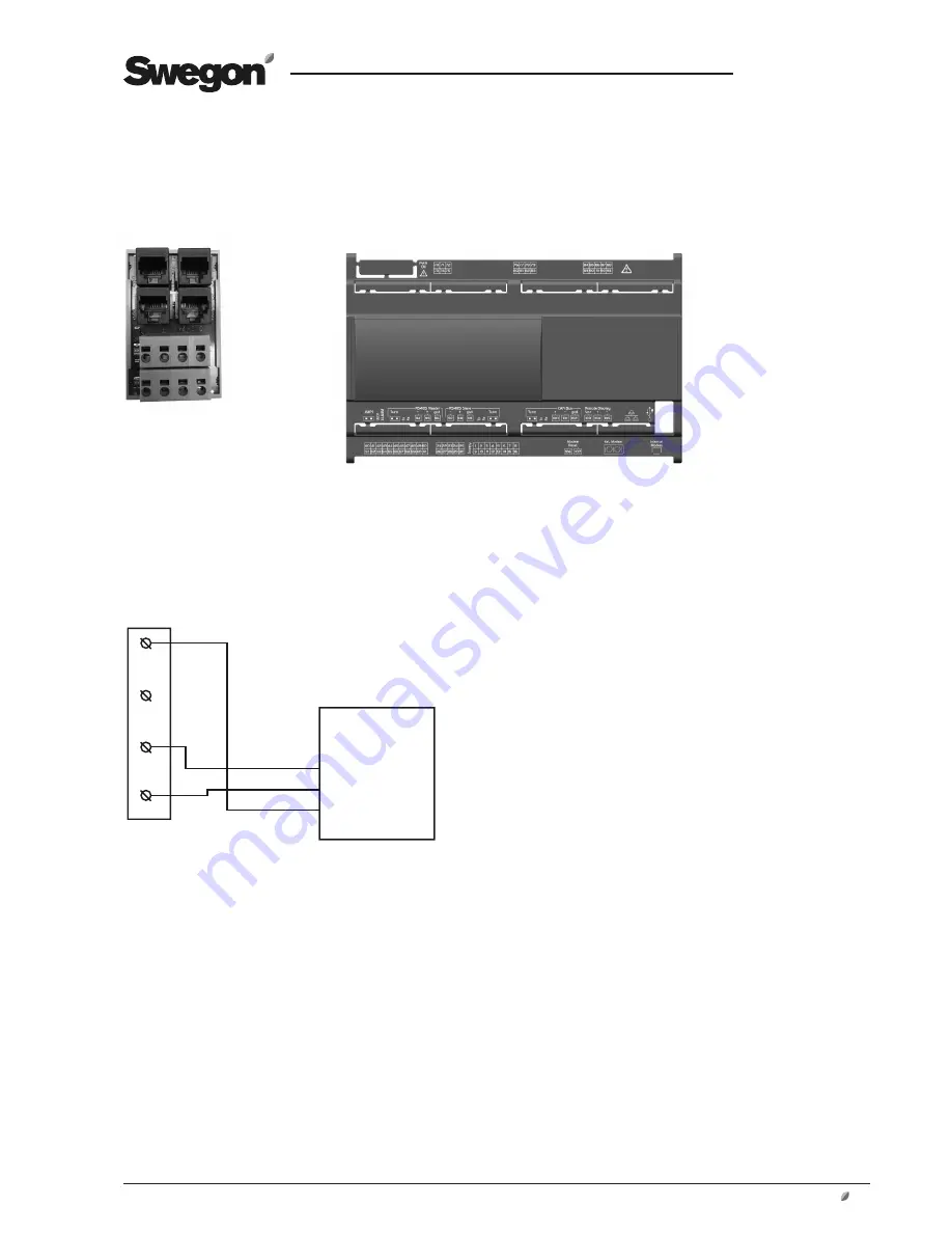
4.1.5 Alternative 5. Connection via external A2 com-
munications interface (RS485 slave)

Wiring terminals for the 
TBLZ-64 cable adapter

1

2

3

4

A2

A2 (RS485 slave)

97 (-)
98 (+)
99 (GND)

Cable adapter (TBLZ-64)

Summary of Contents for IQlogic+

Page 1: ...nsumption The supply air energy to a water coil is controlled by a valve Optimisation of the valve position so that it always strives to be fully open and instead control the water temperature saves e...

Page 2: ...egulate the flow If the temperature by temperature sensor BT50 is higher than the temperature by temperature sensor BT30 the function does not allow valve MF2 to regulate the flow forces it to close O...

Page 3: ...nsor BT50 is higher than the temperature by temperature sensor BT30 the function allows valve MF1 to regulate the flow If the temperature by temperature sensor BT50 is lower than the temperature by te...

Page 4: ...y open 100 the controller decreases the refriger ant temperature setpoint at a rate of 0 3K minute If the optimisation function is allowed and valve MF1 is open less than 80 the controller increases t...

Page 5: ...emperature by temperature sensor BT50 is higher than the temperature by temperature sensor BT30 the function does not allow valve MF2 to regulate the flow forces it to close If dehumification is activ...

Page 6: ...BT1 calls for heating the function transmits a start signal and heating medium setpoint 40 C to the heat pump via Modbus If the temperature by temperature sensor BT50 is higher than the temperature by...

Page 7: ...on is allowed If the optimisation function is allowed and valve MF1 is fully open 100 the controller decreases the refriger ant temperature setpoint at a rate of 0 3K minute If the optimisation functi...

Page 8: ...Links cubicle The chiller s water temperature setpoint is controlled by the GOLD unit and is determined by the cooling load in the ventilation system The temperature setpoint from the AYC function is...

Page 9: ...us contact on the cable adapter The communication cable between the chiller heat pump control equipment and TBLZ 64 cable adapter should be wired according to one of the alternatives below The cables...

Page 10: ...external SMART Link communications interface Wiring terminals SMART Link communications interface Wiring terminals for the TBLZ 64 cable adapter 1 2 3 4 Wiring terminals junction box chiller heat pum...

Page 11: ...Connection via built in SMART Link communications interface Wiring terminals for the TBLZ 64 cable adapter 1 2 3 4 A4 A2 Wiring terminals SMART Link communications interface Communications interface...

Page 12: ...m 4 1 4 Alternative 4 Connection via internal iPro link communications interface ASM1 iPro link SERI1 485 TTL A2 IC208CX Wiring terminals for the cable adapter 1 2 3 4 SERI1 A2 ASM1 Cable adapter TBLZ...

Page 13: ...ight to alter specifications www swegon com 13 4 1 5 Alternative 5 Connection via external A2 com munications interface RS485 slave Wiring terminals for the TBLZ 64 cable adapter 1 2 3 4 A2 A2 RS485 s...

Page 14: ...19 Heat Cool 20 C 21 NO 22 C 23 NO 24 C 25 NO 26 C 27 NO 28 P 29 G 30 G0 31 G 32 G0 24V AC Sensor 1 Sensor 2 Sensor 4 Sensor 3 Com 6 Com 7 Com 8 Com 9 Com 10 Com 11 33 34 G 35 G0 36 Y 37 U 38 39 40 2...

Page 15: ...temperature of the refrig erant and heating medium returning to the chiller heat pump Set the limit for the outdoor temperature mini mum permitted operating temperature The function for the optimizati...

Reviews: