


GB.COOLDX.IN.E.130821
We reserve the right to alter specifications.
4 www.swegon.com
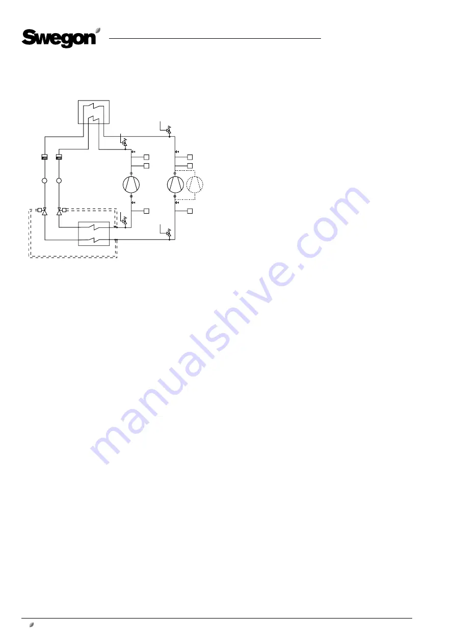
1.2 Basic function diagram
Operation
There are two refrigerant circuits in the cooling unit. The
circuits are separate from one another.
Each circuit is equipped with a finned condenser, a finned
evaporator and a compressor.
The two compressors have different capacity, which ena-
bles control in 3 steps.
The gaseous refrigerant is compressed by compressors M1
and M2 and from there moves on to condenser COND,
where it is chilled by the extract air and is condensed to
liquid form.
The pressure and the temperature decrease as the refri-
gerant in fluid form flows through expansion valves VET1
COND Condenser
VSH1 Overpressure protect. (not COOL DX Top)
VSH2 Overpressure protect. (not COOL DX Top)
B1-1
High pressure sensor
B2-1
Low pressure sensor
B1-2
High pressure sensor
B2-2
Low pressure sensor
BP1-2 Alarm pressure switch for high pressure
BP2-2 Alarm pressure switch for high pressure
M1
Compressor
M2
Compressor
M3
Compressor (size 80 cap.var. 3 only)
VSL1
Underpressure prot. (not COOL DX Top)
VSL2
Underpressure prot. (not COOL DX Top)
EVAP
Evaporator
VET1
Expansion valve with thermostat
VET2
Expansion valve with thermostat
IPL1
Sight glass, refrigerant circuit 1
IPL2
Sight glass, refrigerant circuit 2
FD1
Filter drier
FD2
Filter drier
and VET2.
From the expansion valves the refrigerant moves on to
evaporator EVAP, where the refrigerant evaporates and
chills the outdoor air.
From evaporator EVAP, the evaporated refrigerant is con-
veyed further to the suction side of the compressors where
it is again compressed.
Control
The cooling capacity is regulated in three binary steps by
having one or two compressors in operation.
The cooling compressors are controlled from the GOLD
unit via relays on the IQnomic Plus module mounted in the
COOL DX/COOL DX Top.
Step 1:
When cooling is needed, Compressor M1 is start-
ed.
Step 2:
If more cooling is needed, Compressor M2 starts
and at the same time Compressor M1 stops. An adjust-
able time delay (a step duration of 300 seconds) ensures
that Compressor M2 will not start until Compressor M1 is
operating at full capacity.
Step 3:
If even more cooling is needed, Compressor M1 is
restarted and is run at the same time as Compressor M2.
This third cooling step is also delayed by a preset time de-
lay setting. In addition, the restarting time (300 seconds)
for Compressor M1 shall have expired.
If less cooling is needed and the compressors are subse-
quently switched out step-by-step, there will be no delay
between compressors. The restarting time (300 seconds)
for Compressor M1 shall have expired to enable it to start
again in Step 1 after it has been operated in Step 3.
If any compressor is stopped, the restarting time must
expire before a restart can take place. The restart time is
calculated from one start to the next start.
Low/high pressure sensors B1/B2 measure the pressure
conditions in the system and transmit readings to the
control system to ensure that these are within stipulated
limits.
If the pressure in the cooling circuit becomes too low, or
if the pressure in the condenser circuit becomes too high,
the compressor is stopped and the text PRESSURE LIMIT-
ING is displayed alternately in the hand-held micro termi-
nal of the GOLD air handling unit.
When the restart time has expired, the compressors will try
to restart.
If the pressure increases more, high pressure switches
BP1-2 and BP2-2 will trip and stop the GOLD unit and the
COOL DX cooling unit.
Alarms 164 and 165 will be displayed in the hand-held
micro terminal of the GOLD unit.
Pressure switches BP1-2 and BP2-2 can be manually reset
by pressing a button under each protective sock on the
upper side of the pressure switch. This can be done with-
out removing the protective sock.
COND
VSH2
M1
M2
VSL2
VSL1
EVAP
VET1
VET2
IPL1
IPL2
FD1
FD2
B2-2
HP
B1-2
LP
HP
B2-1
HP
B1-1
LP
HP
BP2-2
BP1-2
VSH1
M3


