16
16
16
The numerical command functions shown in this section are recommended
only for advanced users. Improper use of these commands may interfere
with the functionality of the PTZ system.
The PRO-690 PTZ dome can accept many additional commands to those already
listed. As there are not enough buttons on the remote control to assign one to
each function or setting applicable to the dome, they are presented and used as a
series of numerical commands.
To execute an advanced numerical command function:
•
Press the PRESET, CLEAR (C) or GOTO button (as applicable) on the remote control.
• As all numerical commands are more than a single digit, press the -/-- button.
• Enter the applicable numerical code for the function you wish to execute.
• Press ENTER to confi rm and execute the function.
PRESET Function
62
Set Left limited point
63
Set Right limited point
76
Set Home Point
77
Set Home Point Wait Time to 64 seconds
78
Set Home Point Wait Time to 128 seconds
79
Set Home Point Wait Time to 192 seconds
80
Set Home Point Wait Time to 255 seconds
81
Enable Auto-Home function
82
Disable Auto-Home function
224
Input number 0
225
Input number 1
226
Input number 2
227
Input number 3
228
Input number 4
229
Input number 5
230
Input number 6
231
Input number 7
232
Input number 8
233
Input number 9
234
Input number 10
235
Input number 11
236
Input number 12
237
Input number 13
238
Input number 14
239
Input number 15
240
Init EEPROM to Default
241 Init
System
242
Begin PATTERN setup
243
End PATTERN setup
244
Set PATTERN speed
245
Set PATTERN stay time
246
Set PATTERN point number
247
Start run PATTERN, Enable Auto Start PATTERN cruise
248
Stop run PATTERN, Disable Auto Come Back Home Point
249
Set Pan Limited to 0x38
255
Set Pan/Tilt speed to fast mode
CLEAR
Function
1 -- 32
Clear Preset Point
62
Clear Left Limited Point
63
Clear Right Limited Point
76
Clear Home Point
81
Disable Auto Come Back Home Point
92
Clear Left Limited Point
93
Clear Right Limited Point;
240
Init Pan Tilt to Default
249
Set Pan Limited to 0x3F
GOTO
Function
1 -- 32
Goto Preset Point
34
Goto Pan Zero point
62
Goto Left Limited Point
63
Goto Right Limited Point
76
Goto Home Point
92
Goto Left Limited Point
93
Goto Right Limited Point
96
Stop Auto Scan
99
Start Auto Scan
Advanced Operation
5
5
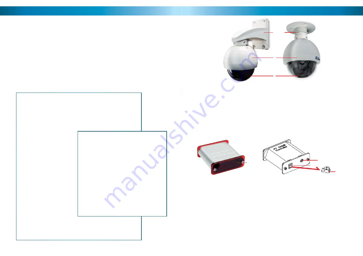
1. Wall-Mount Arm
For mounting the PRO-690 Dome to a wall, post or similar vertical surface.
2. Ceiling-mount Bracket
For mounting the PRO-690 Dome to the underside of a ceiling or overhang.
3. Camera Housing
Contains the camera, PTZ unit and associated circuitry and electronic components.
4. Dome Cover
Protects the camera.
4
nt Arm
1
3
2
5. LED Display
Displays the current status of the PTZ controller.
6. DC 12V
Connect the supplied power adaptor to this socket.
7. RS485 Port
Insert the RS485 plug into this socket.
8. RS485 Plug
Connect the end of the purple and white control wires into this plug, using the attached screws
to secure wires in position. The PURPLE wire is “+”, the WHITE wire is “-”.
8
6
7
Rear View
Front View
5
Layout of the Camera and PTZ Controller


