


73
Included with your NVR is an 8-port PoE switch that gives you the ability to connect an additional eight cameras (of the
same model) to your local network. Just like your NVR, each camera input on the PoE switch provides power to each
camera connected. Please note, connect your provided cameras to the NVR first then connect any additional cameras
to the PoE switch. The PoE switch and the NVR must be connected to the same network for successful connection.
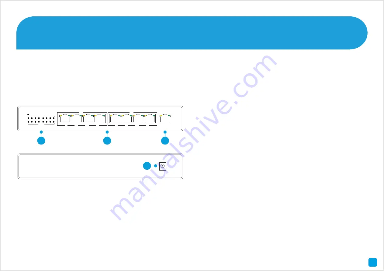
Getting to know your PoE Switch
1) Status LEDs
- The
LEDs will indicate that the
cameras are connected to
your network and will flash
when there is network
activity.
2) Camera Inputs
- Connect
any additional cameras that
you have purchased here.
3) Uplink
- Connect the
supplied Ethernet cable
to the Uplink port then
connect the other end to a
spare port on your router
or wireless access point.
4) Power
- Connect the
supplied power adapter
to the power input then
connect the supplied power
cable to the other end of the
power adapter. Connect
the power connection to a
spare wall socket.
POE
1
2
3
4
POE
5
6
7
8
LINK
ACT
UPLNK
PWR
PoE
LINK
1
2
3
4
5
6
7
8
1
2
3
4


