Suzuki VX800L, Manual
The Suzuki VX800L user manual is essential for maximizing your experience with this top-notch motorcycle. Providing in-depth instructions and helpful tips, this manual is available for free download exclusively at manualshive.com. Streamline your ride and unleash the full potential of your Suzuki VX800L with this comprehensive user manual.
Share
Download


Reviews:
No comments
Related manuals for VX800L

Apache RTR 160 HYPER EDGE 2015
Brand: TVS Pages: 60

SPCOM00000033
Brand: N-Com Pages: 2

Hammer 2005
Brand: Victory Motorcycles Pages: 332

HIGHSIDER VICTORY
Brand: Paaschburg & Wunderlich Pages: 5
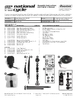
Quantum hardcoated N30214-WK
Brand: National Cycle Pages: 13

F 650 GS
Brand: BMW Pages: 88

640 LC4 Adventure
Brand: KTM Pages: 59

5039505 00 01
Brand: hepco & becker Pages: 2

D3K3-3
Brand: DYNATEK Pages: 5

2005 F4 BRUTALE 910 S
Brand: MV Agusta Pages: 195

F3
Brand: MV Agusta Pages: 467

SX 2
Brand: Shark Pages: 28

ATLANTIC 500
Brand: APRILIA Pages: 170

B901-R
Brand: N-Com Pages: 36

MadAss 50
Brand: Tomberlin Pages: 107

Classic 350 2009
Brand: Royal Enfield Pages: 229

10039294
Brand: Gazzini Pages: 27

10039180
Brand: Gazzini Pages: 60


