background image


4.10 20141208

 (

14 

3.1.3


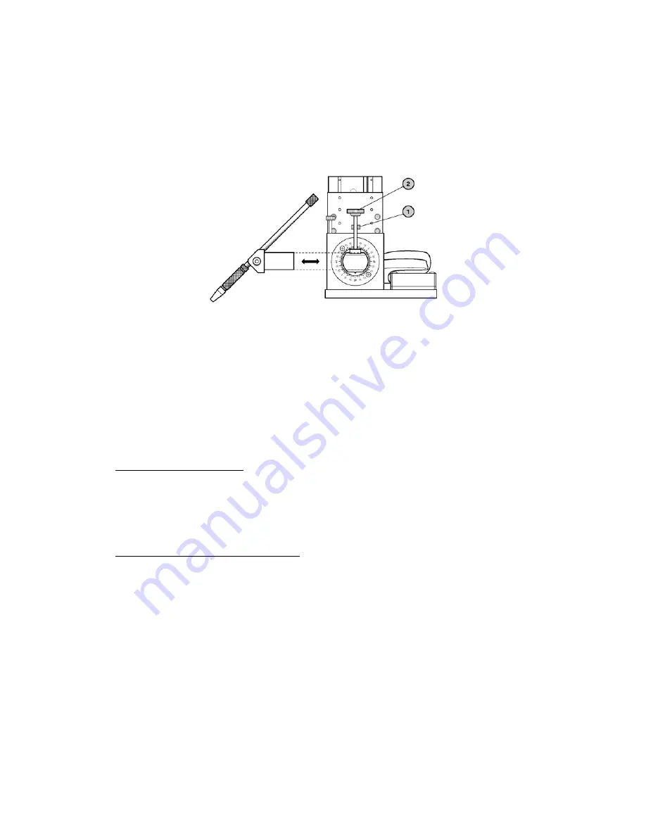
Setting the Angle of Approach of the Micropipette 

The micropipette holder clamp is capable of rotating around its own axis and the movement 
can be locked with the thumbscrew (1) shown here. It is also possible to slide the clamp and 
lock it in place with a separate thumbscrew (2). The clamp itself is spring-loaded, allowing a 
4 mm diameter micropipette holder (not included) to be advanced or retracted easily without 
removing it or risk of it falling out inadvertently. 


Figure 3-2. Micropipette alignment controls. 

These degrees of freedom allow for angles of attack from zero to greater than 45 degrees, 
while at the same time allowing the micropipette holder to be clamped at any point along its 
length. This accommodates a large number of different micropipettes, angled or straight, and 
accessories such as piezo impact drills. When combined with the three fixing patterns on the 
top plate of the mounting adapter, and the sliding action of the mounting adapter, the 
XenoWorks™ Micromanipulator is capable of accommodating any application on a large 
number of microscope platforms. 
The following paragraphs describe factors that affect the setting of the micropipette holder. 

3.1.3.1


Microinjection Chamber 

Some types of microinjection chamber, plastic culture dishes for example, will require a steep 
angle of approach, so that the micropipette clears the sides of the dish (up to 45 degrees). 
Other chambers, depression slides, for example, can accommodate a much shallower angle of 
approach (typically around 10–15 degrees for a depression slide).  

3.1.3.2


Applications and Suggested Setups 

In general, any application in which suspension cells are to be injected or manipulated 
(embryonic stem cell transfer, intracytoplasmic sperm injection, pronuclear zygote injection, 
embryo reconstruction) will require two micropipettes (and thus two micromanipulators), 
one for holding and one for injecting. In this instance, the micropipette tips must approach 
the tissue side-on to prevent the injection micropipette from pushing the tissue off the 
holding pipette. When using a deep dish and angled micropipettes, a 35–45 degree angle of 
attack is appropriate (shown in the figures on the page opposite). If using a depression slide 
and straight micropipettes, an almost flat angle is required as shown in the figures below. 

XENOWORKS MICROMANIPULATOR SYSTEM (TOUCHDECLUTCH) OPERATION MANUAL – REV. 

Summary of Contents for XenoWorks BRM

Page 1: ...orized Micromanipulator System TouchDeclutch Operation Manual Rev 4 10 20141208 Sutter Instrument Company One Digital Drive Novato CA 94949 Voice 415 883 0128 Web www sutter com Fax 415 883 0572 Email...

Page 2: ...RKS MICROMANIPULATOR SYSTEM TOUCHDECLUTCH OPERATION MANUAL REV ii Copyright 2015 Sutter Instrument Company All Rights Reserved XenoWorks is a registered trademark of Sutter Instrument Company 4 10 201...

Page 3: ......

Page 4: ......

Page 5: ...designed for connection to a standard laboratory power outlet Overvoltage Category II and because it is a microprocessor controlled device it should be accorded the same system wiring precautions as...

Page 6: ...nnecting the mechanical units Failure to do this may result in damage to the electronics Operate this instrument only according to the instructions included in this manual Do not operate if there is a...

Page 7: ...rument s instrument is not recommended and if undertaken is done so at the users own risk When transporting the mechanical manipulator be sure to install the shipping screws supplied in their correct...

Page 8: ...4 10 20141208 vi This page intentionally left blank XENOWORKS MICROMANIPULATOR SYSTEM TOUCHDECLUTCH OPERATION MANUAL REV...

Page 9: ...nsion Ring 4 1 4 2 7 Work Position 5 1 4 2 8 Home Position 5 1 4 2 9 Speed 5 1 4 2 10 Z floor 5 1 4 2 11 Micropipette Holder Clamp 5 1 4 2 12 Swing Gate 6 1 4 3 Additional Features and Functions 6 1 4...

Page 10: ...ator 2 Figure 1 2 Joystick 3 Figure 1 3 The rear panel of the joystick 3 Figure 1 4 Joystick height adjustment 4 Figure 1 5 Manipulator Mechanical 6 Figure 1 6 Close up of axis polarity switches 7 Fig...

Page 11: ...and ratings 11 Table C 1 Mains fuse type and ratings 31 Table D 1 Speed settings and ranges of movement 33 Table D 2 Mains fuse type and ratings 34 Table D 3 XenoWorks BRM Controller cables and recep...

Page 12: ...XENOWORKS MICROMANIPULATOR SYSTEM TOUCHDECLUTCH OPERATION MANUAL REV 4 10 20141208 x This page intentionally left blank...

Page 13: ...echnical support is provided by Sutter Instrument Company at no charge to our customers Our technical support staff is available between the hours of 8 00 AM and 5 00 PM Pacific Time at 415 883 0128 Y...

Page 14: ...e working surface and the default axis polarity settings used see Axis Polarity a displacement of the joystick to the left for example will result in concomitant movement of the micromanipulator to th...

Page 15: ...cromanipulator in the X and Y axes are achieved by moving the joystick left and right and forward and backward respectively the switches for establishing axis polarity for right and left handed manipu...

Page 16: ...ip the X and Y movement will remain deactivated for as long as your finger is touching the band The link is reestablished by releasing the touchpad See Operating Instructions for more details on how t...

Page 17: ...manipulator should not be used on the left side of the microscope and vice versa The Home position is a factory preset and cannot be re configured See Operating Instructions for details 1 4 2 9 Speed...

Page 18: ...this and thus protect the user from inadvertently running out of motor travel during an experiment By following the instructions included in this manual use of the Setup function will position each o...

Page 19: ...e is inverted The axis polarity controls are located on the rear of the joystick column Each DIP switch control affects one axis switch 1 reverses the X axis switch 2 reverses the Y axis and switch 3...

Page 20: ...XENOWORKS MICROMANIPULATOR SYSTEM TOUCHDECLUTCH OPERATION MANUAL REV 8 This page intentionally left blank 4 10 20141208...

Page 21: ...l is positioned correctly with respect to the microscope s optical axis Each model microscope will require special Y axis slide settings To determine the appropriate setting for your microscope refer...

Page 22: ...Slide the dovetail on the bottom of the adapter plate into the slide of the microscope adapter it may be necessary to loosen the locknut on the rear of the microscope adapter Do not tighten the locknu...

Page 23: ...e end of travel is reached in the X axis Use the Declutch if necessary Take care not to let the mechanical touch any part of the microscope particularly the condenser Ensuring that the mechanical base...

Page 24: ...XENOWORKS MICROMANIPULATOR SYSTEM TOUCHDECLUTCH OPERATION MANUAL REV 12 See the next section for details on how to align a micropipette at the start of an injecting session 4 10 20141208...

Page 25: ...ith Respect to the Joystick The Declutch mechanism is used to re center the joystick with respect to the micropipette tip This is useful when the micropipette is at the very edge of the microscope fie...

Page 26: ...tforms The following paragraphs describe factors that affect the setting of the micropipette holder 3 1 3 1 Microinjection Chamber Some types of microinjection chamber plastic culture dishes for examp...

Page 27: ...ngled micropipettes ICSI Stem Cell Nuclear Transfer a b Figure 3 4 a and b Suggested approach for suspended cells with straight micropipettes Pronuclear Injection a b Figure 3 5 a and b Suggested appr...

Page 28: ...r either in front or behind the micropipette holder clamp 3 1 4 Memorizing the Work Position This is accomplished by first using the joystick to position the micropipette in the desired Work position...

Page 29: ...pe 2 Slowly rotate the Z axis control clockwise lowering the micropipette towards the bottom of the injection chamber following the micropipette tip down with the microscope s fine focus Use slower sp...

Page 30: ...ette is being replaced by one that is longer the micropipette may crash into the bottom of the injection chamber upon returning to Work from Home Several measures taken alone or together can prevent t...

Page 31: ...the Z axis by rotating the Z axis dial at the bottom of the joystick 8 Once the desired magnification has been reached and the micropipette is still in view set the Work position 9 To replace the micr...

Page 32: ...XENOWORKS MICROMANIPULATOR SYSTEM TOUCHDECLUTCH OPERATION MANUAL REV 20 4 10 20141208 This page intentionally blank...

Page 33: ...or 1 Change the range of movement setting Speed to 2 3 4 or 5 2 The micropipette is too long Use a micropipette that is no longer than about 50mm There is excessive vibration at the micropipette tip...

Page 34: ...e of the chamber consider repositioning the micropipette with respect to the micromanipulator as described in Section 4 1 The micropipette holder clamp has not been tightened down sufficiently Tighten...

Page 35: ...cts the center of the micromanipulator s Y axis Realign the micropipette holder clamp arrangement X and Z axes so that when the micropipette holder is replaced in the clamp the micropipette tip will c...

Page 36: ...is is usually only noticeable at higher magnifications Angled micropipettes should be adjusted from the start so that they are slightly toe down in other words the tip should touch the bottom of the m...

Page 37: ...Ensure that the cable connecting the mechanical to the controller is not under tension coil the cable a few times on the bench surface behind the microscope 4 3 Transporting the Micromanipulator When...

Page 38: ...position 9 Locate the original shipping screws that should have been retained with the original packaging and insert them into the appropriate locations Do not over tighten the screws turn them until...

Page 39: ...s paid for by Sutter Instrument during the first three months this warranty is in effect after which the cost is the responsibility of the customer The limited warranty is as stated above and no impli...

Page 40: ...XENOWORKS MICROMANIPULATOR SYSTEM TOUCHDECLUTCH OPERATION MANUAL REV 28 4 10 20141208 This page intentionally blank...

Page 41: ...cal extension X285305 Z axis horizontal extension X285310 Rotating Base Rotating base 225RBI Mounts Hinged headstage mount 285HEA Adapters Mounting adapter plate X285210 For use with MT and MD series...

Page 42: ...XENOWORKS MICROMANIPULATOR SYSTEM TOUCHDECLUTCH OPERATION MANUAL REV 30 4 10 20141208 This page intentionally blank...

Page 43: ...also stored within the fuse holder The spare fuse is concealed in a compartment as shown To remove the spare fuse press down on the end of the compartment to push it out of the other end The old fuse...

Page 44: ...XENOWORKS MICROMANIPULATOR SYSTEM TOUCHDECLUTCH OPERATION MANUAL REV 32 4 10 20141208 This page intentionally blank...

Page 45: ...ersion 6 position rotary range of movement control Setup function Position memory One user defined set point Work One user defined axis limit Z floor Two preset points Home and Setup Ranges of Movemen...

Page 46: ...connectors Controller Rear Panel Port Connector Receptacle Cable Connector Types Connects to Cable Type Cable Max Length Power entry 3 pin male connector 3 pin power standard female 3 pin male Geograp...

Page 47: ...rly to 67 35 C 95 F Regulatory Safety EN61010 1 CE EMC EN61326 CE Cleaning 70 alcohol or e g UV Dimensions H x W x D Mechanical 112 x 145 x 185 mm 4 4 x 5 7 x 7 3 in Joystick 265 x 240 x 226 mm 10 4 x...

Page 48: ...XENOWORKS MICROMANIPULATOR SYSTEM TOUCHDECLUTCH OPERATION MANUAL REV 3 4 10 20141208 6 This page intentionally blank...

Page 49: ...d Features Micropipette Holder Clamp 5 Frequently used Functions and Features Swing Gate 6 fuse holder 31 location 31 mains 34 replacement 31 spare 31 fuses replacement mains iii 31 G General Informat...

Page 50: ...opipette type 16 Piezo impact drive 16 Working distance 16 Setting the Angle of Attack of the Micropipette 14 specifications cleaning 35 dimensions 35 operating environment 35 regulatory 35 weight 35...

Page 51: ...4 10 20141208 39 NOTES XENOWORKS MICROMANIPULATOR SYSTEM TOUCHDECLUTCH OPERATION MANUAL REV...

Page 52: ...XENOWORKS MICROMANIPULATOR SYSTEM TOUCHDECLUTCH OPERATION MANUAL REV 40 4 10 20141208 NOTES...

Reviews: