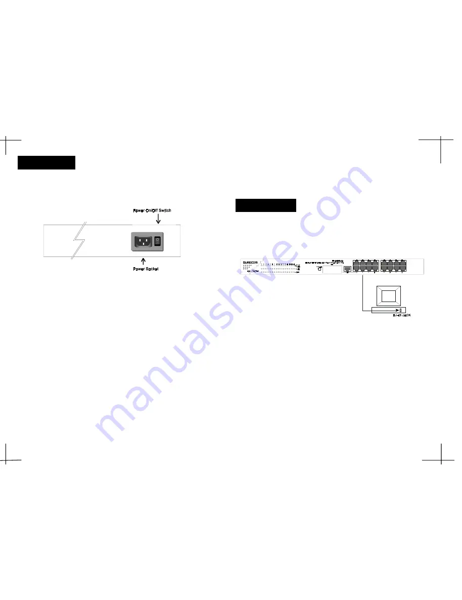
The rear panel consists of an AC power socket and power switch. The system fan for
the Switch Hub is located at the sides of the device.
Figure 2-3: Rear Panel
Rear Panel
1. Power Socket
Plug the power cord into this socket.
2. Power Switch
To turn the power on or off.
2-32-
CHAPTER 3
Network DIY
This chapter describes how to connect this Switch Hub to your Fast Ethernet network.
3. Network Connections
A PC can be connected to the Switch via a twisted-pair Category 3, 4, 5 UTP /STP
straight cable. The PC (equipped with a RJ-45 100/10Mbps jack) should be connected to any
of sixteen ports.
Figure 3-1: PC or Workstation Connection
The LED indicators for PC connection are dependant on the LAN card capabilities. If
LED indicators are not illuminated after making a proper connection, check the PC
LAN card, the cable, Switch conditions and connections.
The following are LED indicator possibilities for a PC to Switch connection:
1. The Link/Act LED indicator illuminates upon hookup.
2. The FDX/Col LED indicator depends upon LAN card capabilities.
3. The 100M LED indicator comes on for a 100 Mbps and stays off for 10Mbps.
○
○
○
○
○
○
○
○
○
○
○
○
○
○
○
○
○
○
○
○
○
○
○
○
○
○
○
○
○
○
○
○
○
○
○
○
○
○
○
○
○
○
○
○
2-3
3-1
Switch to PC
All manuals and user guides at all-guides.com
all-guides.com


