background image

Page 13

24” Set 

Sequoia (SQ) Series  

(cont’d)

30” Set 

18” Set 

Campfire (CF) Series

24” Set 

30” Set 

Summary of Contents for CO18-N

Page 1: ...switch Do not use any telephone in your building Immediately call your gas supplier from a neighbor s telephone Follow the gas suppliers instructions If you cannot reach your gas supplier call the fire department Sure Heat Manufacturing 3130 Moon Station Road Kennesaw GA 30144 Tel 770 422 8008 Fax 770 424 3842 M Mo od de el l R RP P G GO O G GL LO O W WO O C CO O S SO O T TO O S SM MP P 18 24 30 N...

Page 2: ...pening 50 sq in 50 sq in 50 sq in The minimum opening that must be provided by the fireplace chimney to vent the unit properly is shown above in the sizing chart It is necessary to provide adequate combustion and ventilation air Air for combustion and ventilation must not be obstructed Provide adequate clearance around air opening in the combustion chamber and adequate accessibility clearance for ...

Page 3: ...Page 3 ...

Page 4: ...Page 4 ...

Page 5: ... combustion products to vent The unit must be operated with the damper in the fully opened position See Figure 11 Set 18 24 30 Natural Gas 48 000 70 000 70 000 L P Gas 48 000 70 000 70 000 BTU Information 11 Connect pilot and thermocouple to pilot bracket using the screws and nuts provided Be sure that the pilot and the thermocouple is just hanging over the burner pan See Figure 9 NOTE Carefully b...

Page 6: ...Next attach the flared tubing to the burner assembly first then to the gas inlet fitting Avoid kinking the flared tubing while bending If tubing must be cut use a tube cutter Flare the cut end of the tube with a flaring tube Page 6 Burner System Location 1 The Burner system should be located towards the back and centered in the combustion chamber of the vented fireplace The burner system should be...

Page 7: ...each installed burner pan Vermiculite should be sloped to the same angle as the burner pan filling the entire pan See Figure 13 2 Spread glowing embers over the top of the granules or vermiculite covering the entire surface area concentrating on the front and sides of each burner pan for the most realistic burning effect 3 Place log grate over the burner pan See Figure 14 4 Place the 2 back log su...

Page 8: ...Page 8 30 Set 18 Set 24 Set 18 Set 24 Set ...

Page 9: ...Page 9 30 Set 18 Set 24 Set 30 Set 18 Set 24 Set 30 Set ...

Page 10: ...Page 10 18 Set 24 Set 30 Set 18 Set 24 Set 30 Set ...

Page 11: ...Page 11 18 Set Cross Cut CC Series 24 Set Colonial Bark CL Series 30 Set 18 Set 24 Set ...

Page 12: ...Page 12 30 Set Cross Cut CC Series cont d 18 Set Grand Bark GB Series 24 Set 30 Set 18 Set Sequoia SQ Series ...

Page 13: ...Page 13 24 Set Sequoia SQ Series cont d 30 Set 18 Set Campfire CF Series 24 Set 30 Set ...

Page 14: ...Page 14 2 Before lighting smell all around the appliance area for gas Be sure to smell next to the floor because some gas is heavier than air and will settle on floor ...

Page 15: ... become inadequate to heat the thermocouple properly you will need to adjust the pilot See Figure 19 Adjust the height of the Pilot Burner Flame by rotating the Pilot Adjust Screw to the desired 1 2 flame height Remember Be sure to turn the pilot adjust screw 2 full turns in a counter clockwise direction to enable pilot operation Page 15 ...

Page 16: ...Page 16 ...

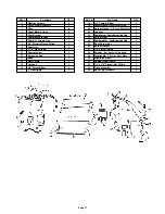
Page 17: ...pple 2 1 2 2 1 1 1 1 1 1 1 1 1 1 1 2 1 REF Part Name QTY 18 19 20 21 22 23 24 25 26 27 28 29 30 31 32 33 34 3 8 Female Elbow Burner Orifice Nat Gas Sets Only Burner Orifice L P Gas Sets Only Locknut SingleBurner SingleBurnerSetsOnly Burner Plug DualBurnerPan DualBurnerSetsOnly Dual Burner Bar Burner Washer 3 8 Flared Tubing Granules Nat Gas Sets Only Sand Vermiculite L P Gas Sets Only Glowing Embe...

Page 18: ..._____________ _______________________________________ _______________________________________ _______________________________________ _______________________________________ _______________________________________ _______________________________________ _______________________________________ _______________________________________ _______________________________________ __________________________...

Page 19: ..._____________ _______________________________________ _______________________________________ _______________________________________ _______________________________________ _______________________________________ _______________________________________ _______________________________________ _______________________________________ _______________________________________ __________________________...

Page 20: ...d reinstallation are the expressed responsibility of the purchaser For repair or replacement of a defective part or parts contact our customer service department at 1 800 229 5647 You will be asked to provide valid warranty registration proof of purchase and model number It is agreed that any repair or replacement is the exclusive remedy from Sure Heat Manufacturing In no case shall Sure Heat be l...

Reviews: