background image


X-Station User Manual


- 40 - 

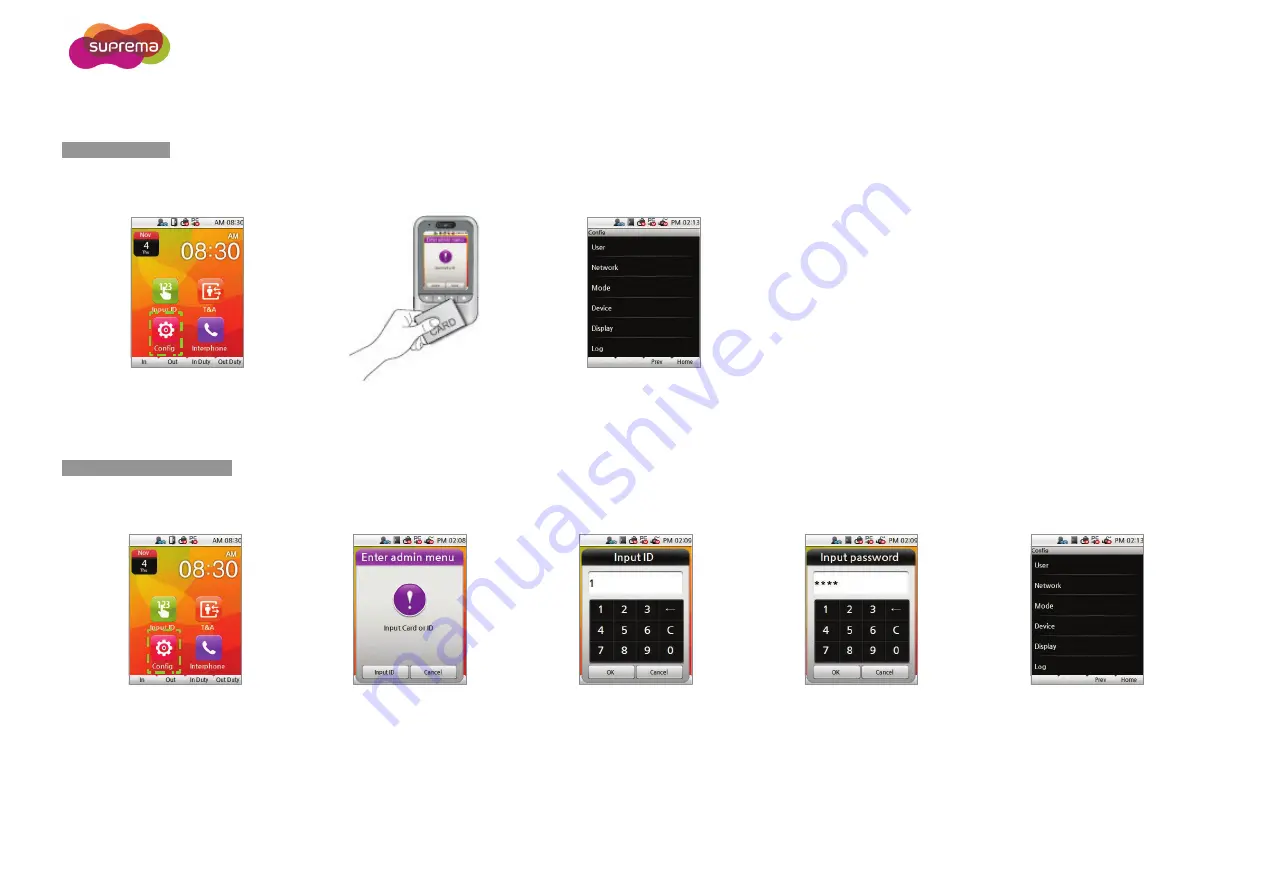
Entering the Admin Menu 


2


Press 

Config

 on the main screen. 

Scan an administrator card 

on the terminal. 

The Admin Menu will appear. 


2


Press 

Config

 on the main screen. 

Scan an administrator card 

on the terminal. 

Enter your ID and press 

OK

Enter the corresponding 

password and press 

OK

The Admin Menu will appear. 


Card Only Mode 

Card/ID + Password Mode 

Summary of Contents for X-station

Page 1: ...X Station User Manual EN 102 00 XST V1 31 www supremainc com...

Page 2: ...he built in camera provides X Station the ability to store image logs perform face detection and feature video intercom capabilities X Station can be directly connected to a PC or server via various i...

Page 3: ...ema dealer for technical support Do not obstruct or place wet objects near or on the vent Do not place liquids such as water beverages and other solutions near on the device Only use the device its in...

Page 4: ...ation 17 Rear Panel 18 Cable Specifications 19 RS485 Cable 19 Ethernet Cable 19 Power and Relay Cable 19 Wiegand I O and TTL Switch Cable 19 RS485 for PC Connection RS232 for Extension Cable 19 Power...

Page 5: ...ce Detection Authorization 31 Using PIN 31 T A Authorization 32 T A Authorization Mode 32 T A Mode 34 Checking Extra T A Events 35 Checking T A and Entrance Records 35 Authorization Failure Screens 36...

Page 6: ...vice Setup 57 Door Setup 57 Time Setup 59 Checking Device Information 60 Checking Memory Information 60 TouchScreen Calibration 61 Device Reset 61 Factory Default 62 Display Sound Setup 63 Log Managem...

Page 7: ...1 Getting Started Components Product Description Dimensions Basic Screen Views Standby Screen Authorization Methods Cards for Authentication...

Page 8: ...s If any of the following items is missing or damage contact your retailer immediately X Station Ferrite Core 1 ea Bracket 1 ea Wall Mount Screws 2 ea PVC Anchors 2 ea Termination resistor 2 ea Softwa...

Page 9: ...X Station User Manual 9 Optional Accessories 12V Power Adapter Secure I O RF Card Plastic Stand Mifare reader writer...

Page 10: ...one 2 Proximity Sensor Turns on LCD backlight when user gets close to sensor 3 Camera Detects and captures face images and videos 4 Touchscreen LCD Used to display the device operating status and devi...

Page 11: ...X Station User Manual 11 Dimensions X Station Wall Mounting Bracket...

Page 12: ...ed 3 T A Accesses additional T A options 4 Interphone Initiates a call if an intercom system has been enabled 5 T A Keys F1 F4 Used to select a T A event 6 Config Accesses the setup menu 7 Input ID Us...

Page 13: ...X Station User Manual 13 Standby Screen Logo Screen Auto T A mode Screen Fix T A mode Screen Announcement Screen Terminal Locked Security mode On Data Transfer mode...

Page 14: ...then perform face detection Scan a registered card then enter the corresponding password Scan a registered card enter the corresponding password and then perform face detection Enter one of three glo...

Page 15: ...sword and then perform face detection Note Refer to Access Authorization for further explanations Cards for Authentication A CSN Card Serial Number is used as the unique identifier for the card A data...

Page 16: ...2 Connection Installation Relay Connections Rear Panel Input Connection Cable Specifications Wiegand Connections Power Connection System Setup Ethernet Connection Network Setup RS485 Connections...

Page 17: ...llation height is extremely important to maximize the performance of the device Select the optimal installation height for all users 1 Place the bracket on the desired location 2 Fix the bracket to th...

Page 18: ...1 3 pin connector RS485 Port 2 Slave device connection 2 5 pin connector Power and relay connection 3 6 pin connector Wiegand I O and TTL Inputs 4 8 pin connector RS485 Port 1 Connection with PC RS232...

Page 19: ...ay Cable Pin Pin Description Wire Color 1 RLY NC ORANGE 2 RLY COM BLUE 3 RLY NO WHITE 4 PWR GND BLACK 5 PWR VDC RED Wiegand I O and TTL Switch Cable Pin Pin Description Wire Color 1 TTL IN1 ORANGE 2 T...

Page 20: ...apter Use a separate power supply for Secure I O electric lock and X Station respectively If connecting and using the power supply to these devices together the devices may malfunction Ethernet Connec...

Page 21: ...al is not sent correctly you should install a terminal resistance at both ends of the bus 120 resistance The signal quality can vary depending on the route so you need to adjust the transmission speed...

Page 22: ...control signal opens the circuit Take care of the direction of the diode Make sure to install the diode near to the door lock Make sure to use different power supplies for the X Station and the door l...

Page 23: ...X Station User Manual 23 Connecting with Automatic Doors Note N O Normally Open A control signal closes the circuit N C Normally Closed A control signal opens the circuit Input Connection...

Page 24: ...X Station User Manual 24 Wiegand Connections Connecting a Wiegand Input Connecting a Wiegand Output Note You can configure the Wiegand Input and Output settings in the BioStar...

Page 25: ...X Station User Manual 25 System Setup Standard Secure Secure I O...

Page 26: ...X Station User Manual 26 Network Setup...

Page 27: ...3 Device Operation Access Authorization T A Authorization...

Page 28: ...n Card Only authentication mode or Bypass Card 1 2 Scan the card on the terminal An authorization success screen will appear Note The default screen will appear when authorization success If no user i...

Page 29: ...within the window shown An authorization success screen will appear Note When the face detection mode is on please fit your face in the frame Using Card and Password Authorization To use password aut...

Page 30: ...face within the window shown An authorization success screen will appear Using Card and Password Authorization To use password authorization use Auth Mode with the ID Card Password setup 1 2 3 4 Pres...

Page 31: ...Position your face within the window shown An authorization success screen will appear Using PIN PIN authorization is operated in PIN Only authentication mode If you use PIN authorization select Confi...

Page 32: ...ed T A event F1 F4 Scan the card on the terminal An authorization success screen will appear and the T A event will be logged Note You can use Face Detection mode with T A mode When the Face Detection...

Page 33: ...OK An authorization success screen will appear and the T A event will be logged 1 2 3 4 5 Press the desired T A event F1 F4 Press Input ID Enter your ID and then press OK Enter your password and then...

Page 34: ...is set to Auto the device will automatically log a scheduled T A event upon authentication The T A event schedule can be set using BioStar Different T A events can still be manually logged using the...

Page 35: ...t work after offsite work leaving work after offsite work returning after offsite work etc Press T A on the main screen to select extra T A events Extra T A events screen Checking T A and Entrance Rec...

Page 36: ...ion fails the screen is displayed as follows Auth Mode setting does not match Authorization interval was invalid The maximum number of authorizations was exceeded User is not in the authorization grou...

Page 37: ...4 Device Configuration Admin Settings User Management Data Card User Management Network Setup Mode Setup Device Setup Display Sound Setup Log Management...

Page 38: ...immediately after the first installation The Admin enables to add delete user and configure device setting 1 2 3 4 Press Config on the main screen Select User Select Enroll User Check the Admin box 5...

Page 39: ...ss Card will be authorized by bypass regardless of the Auth Mode Users who are registered with the Private Auth mode will have priority in the terminal s Auth mode and be authorized in Private Auth Th...

Page 40: ...an an administrator card on the terminal The Admin Menu will appear 1 2 3 4 5 Press Config on the main screen Scan an administrator card on the terminal Enter your ID and press OK Enter the correspond...

Page 41: ...nt Camera Event PIN Only PIN Only PIN 1 PIN 2 PIN 3 4 Device Door Relay Driven By Duration sec RTE Input Type Door Sensor Input Type Held Open Unlock Time Lock Time Time Date Time Time Sync Device Inf...

Page 42: ...ct Enroll User Do not check the box Admin when registering a user Enter the user ID The user ID can be created numbers 1 to 4294967295 6 7 8 9 10 Scan the card on the terminal Enter the name You can o...

Page 43: ...en will appear Note Users who are registered with a Bypass Card will be authorized by bypass regardless of the Auth Mode Users who are registered with Private Auth will have priority in the terminal s...

Page 44: ...red user Make the desired changes and then press Add or F4 An enroll success screen will appear Deleting Users 1 2 3 4 5 Select User Select Search Use a search method to find the user See User Search...

Page 45: ...rs to be deleted and then press Delete or F4 Press OK to delete the selected users 1 2 3 Select User Click Delete All Users Press OK to delete all users Attention You cannot restore user data that is...

Page 46: ...and press OK Enter the user ID and press OK The corresponding ID search results will appear 1 2 3 4 5 Select User Select Search Select Search by Name and press OK Enter the name and press OK The corr...

Page 47: ...ace the CSN Card on the X Station The corresponding CSN search results will appear Checking the Registered User Information 1 2 3 Select User Select Enrolled user Info Press OK to return to the previo...

Page 48: ...Card is used the user data will not be saved on the terminal but on to the card The user data must be managed separately 1 2 3 4 Press Config on the main screen Select User Select Enroll Data Card En...

Page 49: ...ar Note Bypass cards provide authorization independent of the Auth Mode Access Groups can be configured using BioStar and is used to restrict access to certain devices CSN Cards and Data Cards cannot...

Page 50: ...ort for the device Default 1470 Max Conn Set the max number of BioStar connections to the device DHCP Enable Disable the DHCP When DHCP is enabled the IP address Gateway and Subnet will be disabled IP...

Page 51: ...ice and a BioStar server 1 2 3 Select Network Select Server Setup the use of server IP and port press Prev or Home to activate the settings Server Enable Disable Server Mode for the device Server IP E...

Page 52: ...communication Setting values 9600 19200 57600 115200 Serial Mode Set the desired RS485 communication mode NET HOST allows slave devices to be connect to the device NET SLAVE allows the device to conne...

Page 53: ...bled a face must be detected before authorization is granted Dual Requires two consecutive authentications of two different users within 15 seconds before authorization is granted Card Mode Set the ca...

Page 54: ...can only authorize by Bypass Card You cannot enter the Admin Menu with authorization with ID Card so have to register a Bypass Card when registering user T A Mode Setup Set up the T A mode for the dev...

Page 55: ...ough BioStar 1 2 3 Select Mode Select T A event Program the desired location for each T A event Setting Camera Event Triggers Sets event triggers for image capture Timezones for the camera events can...

Page 56: ...etup for Authentication Sets a global PIN for general authentication Up to three global PIN numbers can be registered 1 2 3 4 Select Mode Select PIN Only Check PIN Only and select a PIN to create Ente...

Page 57: ...rdware ID of the selected device must be entered Driven by Select the event s that will trigger the relay All events Associated devices will open the door on any successful authorization events Auth A...

Page 58: ...s Not Use Input0 Input1 SIO0 Input0 3 SIO1 Input0 3 SIO2 Input0 3 SIO3 Input0 3 Held Open Set the duration after which to trigger a held open door alarm Unlock Time Select the schedule for which the d...

Page 59: ...data time and time sync Date Set the current date YYYY MM DD and press OK Time Set the current time hh mm ss and press OK Time Sync Check Time Sync to synchronize the device time with the server time...

Page 60: ...mation Displays key device information 1 2 3 Press Device Select Device Info Various device specific information will be displayed Checking Memory Information 1 2 3 Press Device Select Memory Info The...

Page 61: ...e the point of contact with the user interface 1 2 3 4 Press Device Select Calibration Keep pressing the cross on the screen until the calibration is complete Calibration success screen will pop up on...

Page 62: ...e next page Select Factory Default Press OK to reset all settings to factory default Warning Factory default will change all settings to its factory defaults Wallpapers sound effects notice etc will a...

Page 63: ...ection Theme 1 Theme 2 Theme 3 Background Select a background style for the standby screen Selection Logo Notice Slide Show Timeout Select the amount of idle time required before returning to the home...

Page 64: ...ffects Selection 0 100 Language Select the language displayed on the terminal You have to reboot the terminal to activate language changes Selection Korean English Custom Time Select whether the time...

Page 65: ...cking the Log List Log records can be viewed directly from the terminal 1 2 3 4 1 4 2 Click Log Select Log List Click on a log record to view details Displays detailed information of the log event Log...

Page 66: ...e all logs Delete success screen will pop up on the screen Checking Log Information 1 2 3 Click Log Select Log Info Displays the number of logs stored on the terminal Click OK to return to the previou...

Page 67: ...Appendix Product Specifications Electrical Specification FCC Rules Font License...

Page 68: ...isplay 3 5 color touch screen LCD Display 3 5 color touch screen Operating Temperature 20 C 50 C Humidity 90 Tamper Switch Operating Voltage 12V DC Dimensions 79mm W x 135mm H x 19 15 mm D Electrical...

Page 69: ...the receiving antenna 2 Increase the separation between the eq uipment and receiver 3 Connect the equipment into an outlet on a circuit difference from that to which the receiver is connected 4 Consul...

Page 70: ...ders or in the appropriate machine readable metadata fields within text or binary files as long as those fields can be easily viewed by the user 3 No Modified Version of the Font Software may use the...

Page 71: ...Suprema Inc 16F Parkview Tower 6 Jeongja Bundang Seongnam Gyeonggi 463 863 Korea Tel 82 31 783 4502 Fax 82 31 710 4503 Email sales supremainc com Homepage www supremainc com...

Reviews: