background image

Chapter 2: Installation

2-29

JF2

JSD1

SW1

JIPMB1

J21

JBT1

LEB1

LEB2

LE3

JI2C2 JI2C1

JNMI1

JRST1

JWD1

JPME2

JIB1

JWP1

JPL1

JPG1

JBAT1

JTPM1

P2 DIMMF1 P2 DIMME1

XDP-CPU

COM1

VGA

S-SA
TA0

Always DIMMxA

 First

CPU1_Port2 SXB1 PCI-E 3.0 x16

LAN1

IPMI_LAN

USB0/1

LAN2

USB2

P1 DIMMC1

UID

P1 DIMMD1

X9DRT-HF

Rev. 1.21

BIOS

P1 DIMMB1

FP

 CTRL

PWR SPPL

Y

PCH

IB CTRL

InfiniBand

Connector

LAN CTRL

BMC

PCI-Ex16 (Proprietary)

P2 DIMMH1

J4

LE1

LE2

JPB1

JB2

JB3

JB1

LEM1

S-SA
TA2

I-SA
TA1

I-SA
TA0

P1 DIMMA1

JPME1

CPU1_Port3A

 SXB2

 PCI-E 3.0 X8

CPU2_Port2C SXB3

 PCI-E 3.0 X8

S-SA
TA3

CLOSE 1st

OPEN 1st

CPU2

P2 DIMMG1

CPU1

CLOSE 1st

OPEN 1st

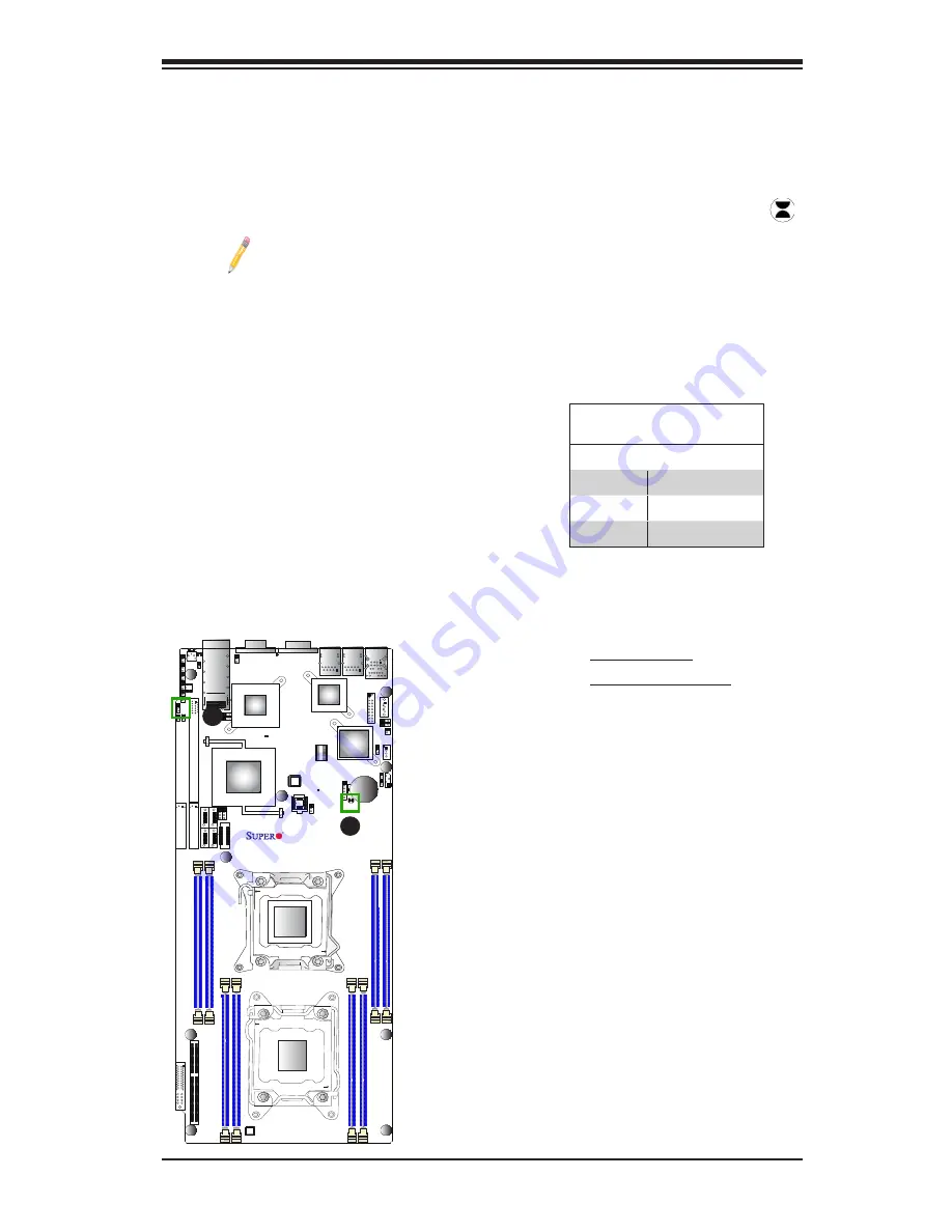
CMOS Clear

JBT1 is used to clear CMOS. Instead of pins, this "jumper" consists of contact pads 
to prevent accidental clearing of CMOS. To clear CMOS, use a metal object such 
as a small screwdriver to touch both pads at the same time to short the connection. 
Always remove the AC power cord from the system before clearing CMOS.

Note 1:

 For an ATX power supply, you must completely shut down the 

system, remove the AC power cord, and then short JBT1 to clear CMOS.

Note 2:

 Be sure to remove the onboard CMOS Battery before you short 

JBT1 to clear CMOS.

Note 3:

 Clearing CMOS will also clear all passwords.

A. Clear CMOS
B. Watch Dog Enable

Watch Dog Enable/Disable

Watch Dog (JWD1) is a system monitor that 
can reboot the system when a software ap-
plication hangs. Close pins 1-2 to reset the 
system if an application hangs. Close pins 
2-3 to generate non-maskable interrupt sig-
nals for the application that hangs. See the 
table on the right for jumper settings. Watch 
Dog must also be enabled in the BIOS.

Watch Dog 

Jumper Settings

Jumper Setting     Definition     

Pins 1-2

Reset (default)

Pins 2-3

NMI

Open

Disabled

A

B

Summary of Contents for X9DRT-HF

Page 1: ...USER S MANUAL Revision 1 0c X9DRT HF X9DRT HIBQF X9DRT HIBFF...

Page 2: ...UCH DAMAGES IN PARTICULAR SUPER MICRO COMPUTER INC SHALL NOT HAVE LIABILITY FOR ANY HARDWARE SOFTWARE OR DATA STORED OR USED WITH THE PRODUCT INCLUDING THE COSTS OF REPAIRING REPLACING INTEGRATING INS...

Page 3: ...mory This motherboard is ideal for 2U server platforms Please refer to our website http www supermicro com for processor and memory support updates Manual Organization Chapter 1 describes the features...

Page 4: ...t damage to the system or injury to yourself Warning Important information given to ensure proper system installation or to prevent damage to the components Note Additional information given to differ...

Page 5: ...icro Computer B V Het Sterrenbeeld 28 5215 ML s Hertogenbosch The Netherlands Tel 31 0 73 6400390 Fax 31 0 73 6416525 Email sales supermicro nl General Information support supermicro nl Technical Supp...

Page 6: ...ized Warning Statements 2 1 Battery Handling 2 1 Product Disposal 2 3 2 2 Static Sensitive Devices 2 4 Precautions 2 4 Unpacking 2 4 2 3 Processor and Heatsink Installation 2 5 Installing the LGA2011...

Page 7: ...GLAN Enable Disable 2 28 CMOS Clear 2 29 Watch Dog Enable Disable 2 29 VGA Enable 2 30 BMC Enable 2 30 I2 C Bus to PCI Exp Slots 2 31 InfiniBand IB Enable For X9DRT HIBQF HIBFF 2 31 Management Engine...

Page 8: ...ce 3 8 Chapter 4 BIOS 4 1 Introduction 4 1 4 2 Main Setup 4 2 4 3 Advanced Setup Configurations 4 3 4 4 Event Logs 4 21 4 5 IPMI 4 23 4 6 Boot 4 25 4 7 Security 4 26 4 8 Save Exit 4 27 Appendix A BIOS...

Page 9: ...ndards in quality and performance This motherboard was designed to be used in a 2U Twin 2 Twin Superserver system Note For your system to work properly please follow the links below to download all ne...

Page 10: ...InfiniBand No Yes Yes FDR IB No No Yes QDR IB No Yes No Note All graphics shown in this manual were based upon the latest PCB Revision available at the time of publishing of the manual The motherboard...

Page 11: ...to http www supermicro com products nfo files IPMI Best_Practices_BMC_Security pdf Motherboard Layout JF2 JSD1 SW1 JIPMB1 J21 JBT1 LEB1 LEB2 LE3 JI2C2 JI2C1 JNMI1 JRST1 JWD1 JPME2 JIB1 JWP1 JPL1 JPG1...

Page 12: ...d See Page 2 16 in Chapter 2 for details X9DRT HF HIBQF HIBFF Motherboard Quick Reference JF2 JSD1 SW1 JIPMB1 J21 JBT1 LEB1 LEB2 LE3 JI2C2 JI2C1 JNMI1 JRST1 JWD1 JPME2 JIB1 JWP1 JPL1 JPG1 JBAT1 JTPM1...

Page 13: ...ary Add On Riser Card CPU1_Port3A SXB2 PCI E 3 0 x8 Slot for SMB Proprietary Riser Card CPU2_Port2C SXB3 PCI E 3 0 x8 Slot for SMB Proprietary Add On Daughter Card IB InfiniBand Connector X9DRT HIBQF...

Page 14: ...een On HDD SATA Active LEB1 InfiniBand Link LED Green On IB Connected X9DRT HIBQF HIBFF LEB2 InfiniBand Activity LED Yellow On IB Active X9DRT HIBQF HIBFF LEM1 BMC Heartbeat LED Green Blinking BMC Nor...

Page 15: ...latest memory updates please refer to the Tested Memory List posted on our website http www supermicro com products motherboard Virtualization VT x VT d and VT c Chipset Intel PCH C602 Expansion One 1...

Page 16: ...Soft Off Power on mode for AC power recovery Intel Intelligent Power Node Manager available when the NMView utility is installed Management Engine PC Health CPU Monitoring Monitoring Onboard voltage m...

Page 17: ...on Header and Detection Dimensions 6 80 L x 16 64 W 172 72 mm x 422 66 mm Note 1 For IPMI Configuration Instructions please refer to the Embedded BMC Configuration User s Guide available http www supe...

Page 18: ...DMI PEG1_4 1 USB LAN i350 2 ports SATA AT25321 LPC CPU FRONT FAN Side CPU REAR I O Side PCI 32 bit USB REAR 0 1 2 H F E Socket 0 Socket 1 1 P0 P0 P1 P1 PE3 PE2 PE1 DMI PE3 PE2 PE1 DMI Gen3 x16 x4 VGA...

Page 19: ...0 GT s providing superb system performance and functionality enhancement The PCH C602 chipset provides extensive IO support including the following functions and capabilities PCI Express Rev 2 0 suppo...

Page 20: ...er can adjust the voltage thresholds to define the sensitivity of the voltage monitor Environmental Temperature Control A thermal control sensor monitors the CPU temperature in real time and will turn...

Page 21: ...s 2008 Operating Systems Slow Blinking LED for Suspend State Indicator When the CPU goes into a suspend state the chassis power LED will start blinking to indicate that the CPU is in suspend mode When...

Page 22: ...when the NMView software is installed The Intel Intelligent Power Node Manager IPNM provides your system with real time thermal control and power management for maximum energy efficiency Although IPN...

Page 23: ...es 32 bit 33 MHz 3 3V PCI interface which is compliant with the PCI Local Bus Specification Rev 2 3 The PCI system interface connects to the onboard PCI Bridge used by the graphics controller Other Fe...

Page 24: ...HIBQF HIBFF Motherboard User s Manual RMCP protocol supported Note For BMC Configuration Instructions please refer to the Embedded BMC Configuration User s Guide available http www supermicro com sup...

Page 25: ...omponents Read this section in its entirety before installing or configuring components in the Supermicro chassis Battery Handling Warning There is a danger of explosion if the battery is replaced inc...

Page 26: ...o de explosi n si la bater a se reemplaza de manera incorrecta Re emplazar la bater a exclusivamente con el mismo tipo o el equivalente recomen dado por el fabricante Desechar las bater as gastadas se...

Page 27: ...dieses Produkts sollte gem allen Bestimmungen und Gesetzen des Landes erfolgen Advertencia Al deshacerse por completo de este producto debe seguir todas las leyes y regla mentos nacionales Attention L...

Page 28: ...removing the board from the antistatic bag Handle the board by its edges only do not touch its components peripheral chips memory modules or gold contacts When handling chips or modules avoid touching...

Page 29: ...t you use an Intel certified multi directional heatsink only Make sure to install the system board into the chassis before you install the CPU heatsink When receiving a motherboard without a processor...

Page 30: ...rs the CPU socket from its locking position 3 With the Close 1st lever fully retracted gently push down on the Open 1st lever to open the load plate Lift the load plate to open it completely OPEN1st W...

Page 31: ...t Do not drop the CPU on the socket Do not move the CPU horizontally or vertically Do not rub the CPU against the surface or against any pins of the socket to avoid damaging the CPU or the socket Sock...

Page 32: ...ly installed 5 Close the load plate with the CPU inside the socket Lock the Close 1st lever first then lock the Open 1st lever second Use your thumb to gently push the load levers down to the lever lo...

Page 33: ...components installed in your system Installing a Passive CPU Heatsink 1 Apply the proper amount of thermal grease to the heatsink 2 Place the heatsink on top of the CPU so that the two mounting holes...

Page 34: ...tsink to avoid damaging the CPU or other components 1 Unplug the power cord from the power supply 2 Press down the push pin on the heatsink and turn counter clock wise to loosen it Repeat the same ste...

Page 35: ...installing or removing DIMM modules to prevent any possible damage Installing Removing DIMMs 1 Insert the desired number of DIMMs into the memory slots starting with P1 DIMMA1 For best performance ple...

Page 36: ...er board Processor Memory Module Population Configuration For memory to work properly follow the tables below for memory installation Processors and their Corresponding Memory Modules CPU Correspondin...

Page 37: ...ite at http www supermicro com support resources mem cfm Populating RDIMM ECC Memory Modules Intel E5 2600 v2 Series Processor RDIMM Memory Support Ranks Per DIMM Data Width Memory Capacity Per DIMM S...

Page 38: ...ces mem cfm Populating RDIMM ECC Memory Modules Intel E5 2600 Series Processor RDIMM Memory Support Ranks Per DIMM Data Width Memory Capacity Per DIMM See the Note Below Speed MT s and Voltage Validat...

Page 39: ...ks Per DIMM Data Width Memory Capacity Per DIMM See the Note Below Speed MT s and Voltage Validated by Slot per Channel SPC and DIMM Per Channel DPC 2 Slots Per Channel 3 Slots Per Channel 1DPC 2DPC 1...

Page 40: ...f chassis Make sure that the locations of all the mounting holes for both motherboard and chassis match Although a chassis may have both plastic and metal mounting fas teners metal ones are highly rec...

Page 41: ...assis as needed 5 Install the motherboard into the chassis carefully to avoid damaging mother board components 6 Using the Phillips screwdriver insert a Pan head 6 screw into a mounting hole on the mo...

Page 42: ...LEM1 S SATA2 I SATA1 I SATA0 P1 DIMMA1 JPME1 CPU1_Port3A SXB2 PCI E 3 0 X8 CPU2_Port2C SXB3 PCI E 3 0 X8 S SATA3 CLOSE 1st OPEN 1st CPU2 P2 DIMMG1 CPU1 CLOSE 1st OPEN 1st 2 6 Control Panel Connectors...

Page 43: ...LEM1 S SATA2 I SATA1 I SATA0 P1 DIMMA1 JPME1 CPU1_Port3A SXB2 PCI E 3 0 X8 CPU2_Port2C SXB3 PCI E 3 0 X8 S SATA3 CLOSE 1st OPEN 1st CPU2 P2 DIMMG1 CPU1 CLOSE 1st OPEN 1st Universal Serial Bus USB Two...

Page 44: ...A SXB2 PCI E 3 0 X8 CPU2_Port2C SXB3 PCI E 3 0 X8 S SATA3 CLOSE 1st OPEN 1st CPU2 P2 DIMMG1 CPU1 CLOSE 1st OPEN 1st 1 LAN 1 2 LAN 2 3 IPMI_LAN 1 2 3 Ethernet Ports Two Gigabit Ethernet ports LAN1 2 ar...

Page 45: ...PB1 JB2 JB3 JB1 LEM1 S SATA2 I SATA1 I SATA0 P1 DIMMA1 JPME1 CPU1_Port3A SXB2 PCI E 3 0 X8 CPU2_Port2C SXB3 PCI E 3 0 X8 S SATA3 CLOSE 1st OPEN 1st CPU2 P2 DIMMG1 CPU1 CLOSE 1st OPEN 1st 1 2 Serial Po...

Page 46: ...formance computing See the table below for pin definitions 1 InfiniBand 1 Pin Description 1 Ground 2 Transmitter Inverted Data Input 3 Transmitter Non Inverted Data Input 4 Ground 5 Transmitter Invert...

Page 47: ...t pin 16 on JF2 The Rear UID Switch is located at SW1 next to the InfiniBand Connector The Front Panel UID LED is located at pin 17 of JF2 and the Rear UID LED is located at LE2 When the user presses...

Page 48: ...the layout below for the location of JF2 JF2 JSD1 SW1 JIPMB1 J21 JBT1 LEB1 LEB2 LE3 JI2C2 JI2C1 JNMI1 JRST1 JWD1 JPME2 JIB1 JWP1 JPL1 JPG1 JBAT1 JTPM1 P2 DIMMF1 P2 DIMME1 XDP CPU COM1 VGA S SATA0 Alwa...

Page 49: ...LEM1 S SATA2 I SATA1 I SATA0 P1 DIMMA1 JPME1 CPU1_Port3A SXB2 PCI E 3 0 X8 CPU2_Port2C SXB3 PCI E 3 0 X8 S SATA3 CLOSE 1st OPEN 1st CPU2 P2 DIMMG1 CPU1 CLOSE 1st OPEN 1st 2 7 Connecting Cables A NMI...

Page 50: ...TA2 I SATA1 I SATA0 P1 DIMMA1 JPME1 CPU1_Port3A SXB2 PCI E 3 0 X8 CPU2_Port2C SXB3 PCI E 3 0 X8 S SATA3 CLOSE 1st OPEN 1st CPU2 P2 DIMMG1 CPU1 CLOSE 1st OPEN 1st A System Reset B DOM PWR Connector A B...

Page 51: ...ATA1 I SATA0 P1 DIMMA1 JPME1 CPU1_Port3A SXB2 PCI E 3 0 X8 CPU2_Port2C SXB3 PCI E 3 0 X8 S SATA3 CLOSE 1st OPEN 1st CPU2 P2 DIMMG1 CPU1 CLOSE 1st OPEN 1st A SATA DOM PWR B TPM Port80 A TPM Header Port...

Page 52: ...DIMMG1 CPU1 CLOSE 1st OPEN 1st A 2 8 Jumper Settings Explanation of Jumpers To modify the operation of the mother board jumpers can be used to choose between optional settings Jumpers cre ate shorts...

Page 53: ...ar CMOS use a metal object such as a small screwdriver to touch both pads at the same time to short the connection Always remove the AC power cord from the system before clearing CMOS Note 1 For an AT...

Page 54: ...1 CPU1_Port3A SXB2 PCI E 3 0 X8 CPU2_Port2C SXB3 PCI E 3 0 X8 S SATA3 CLOSE 1st OPEN 1st CPU2 P2 DIMMG1 CPU1 CLOSE 1st OPEN 1st A VGA Enabled B BMC Enabled VGA Enable Jumper JPG1 allows the user to en...

Page 55: ...for jumper settings I2 C to PCI Exp Jumper Settings Jumper Setting Definition 1 2 Enabled 2 3 Disabled Default JF2 JSD1 SW1 JIPMB1 J21 JBT1 LEB1 LEB2 LE3 JI2C2 JI2C1 JNMI1 JRST1 JWD1 JPME2 JIB1 JWP1 J...

Page 56: ...the user to flash the system firmware from a host server for system setting modifications See the table on the right for jumper settings ME Mode Select Jumper Settings Jumper Setting Definition 1 2 N...

Page 57: ...lane USB ports 0 1 on the motherboard The amber LED on the right indicates activity while the green LED on the left indicates the speed of the connec tion See the table on the right for more informati...

Page 58: ...3 CLOSE 1st OPEN 1st CPU2 P2 DIMMG1 CPU1 CLOSE 1st OPEN 1st Onboard Power LED An Onboard Power LED is located at LE1 on the motherboard When this LED is on the system is on Be sure to turn off the sys...

Page 59: ...olor Status Definition Green Solid InfiniBand Connected Off Off No connection InfiniBand LED Indicators LEB1 LEB2 For the X9DRT HIBQF HIBFF Only Two InfiniBand LED Indicators LEB1 LEB2 are located on...

Page 60: ...nit Identified JF2 JSD1 SW1 JIPMB1 J21 JBT1 LEB1 LEB2 LE3 JI2C2 JI2C1 JNMI1 JRST1 JWD1 JPME2 JIB1 JWP1 JPL1 JPG1 JBAT1 JTPM1 P2 DIMMF1 P2 DIMME1 XDP CPU COM1 VGA S SATA0 Always DIMMxA First CPU1_Port2...

Page 61: ...PU1_Port3A SXB2 PCI E 3 0 X8 CPU2_Port2C SXB3 PCI E 3 0 X8 S SATA3 CLOSE 1st OPEN 1st CPU2 P2 DIMMG1 CPU1 CLOSE 1st OPEN 1st 2 10 PCI Express and Serial ATA Connections A C B PCI Express 3 0 x16 Slot...

Page 62: ...2C SXB3 PCI E 3 0 X8 S SATA3 CLOSE 1st OPEN 1st CPU2 P2 DIMMG1 CPU1 CLOSE 1st OPEN 1st D E F Note For more information on IPMI configuration please refer to the WPCM 450 IPMI BMC User s Guide posted o...

Page 63: ...motherboard and chassis 2 Disconnect all ribbon wire cables from the motherboard including those for the keyboard and mouse 3 Remove all add on cards 4 Install CPU 1 first making sure that it is full...

Page 64: ...unplugging the power cord and contracting both pads on the CMOS Clear Jumper JBT1 Refer to Section 2 8 in Chapter 2 2 Remove all components from the motherboard especially the DIMM mod ules Make sure...

Page 65: ...their slots Follow the instructions given in Section 2 4 in Chapter 2 6 Please follow the instructions given in the DIMM Population Tables listed in Section 2 4 to install your memory modules When th...

Page 66: ...king properly 3 Using minimum configuration for troubleshooting Remove all unnecessary components starting with add on cards first and use minimum configuration with a CPU and a memory module installe...

Page 67: ...s chapter or see the FAQs on our Website http www supermicro com before contacting Technical Support 2 BIOS upgrades can be downloaded from our Website http www supermicro com 3 If you still cannot re...

Page 68: ...efully Do not damage the battery in any way a damaged battery may release hazardous materials into the environment Do not discard a used battery in the garbage or a public landfill Please comply with...

Page 69: ...re downloading You can choose from the zip file and the exe file If you choose the zip BIOS file please unzip the BIOS file onto a bootable USB device Run the batch file using the format AMI bat filen...

Page 70: ...rominently displayed on the outside of the shipping carton and the shipping package is mailed prepaid or hand carried Shipping and handling charges will be applied for all orders that must be mailed w...

Page 71: ...ed by the user The right frame displays the key legend Above the key legend is an area reserved for a text message When an option is selected in the left frame it is highlighted in white Often a text...

Page 72: ...ade the BIOS unless your system has a BIOS related issue Flashing the wrong BIOS can cause irreparable damage to the system In no event shall the manufacturer be liable for direct indirect special inc...

Page 73: ...tion Total Memory This displays the amount of memory that is available in the system 4 3 Advanced Setup Configurations Use the arrow keys to select Advanced Setup and press Enter to access the followi...

Page 74: ...s set to Disabled the ROM BIOS of the host adap tors will not capture Interrupt 19 and the drives attached to these adaptors will not function as bootable devices The options are Enabled and Disabled...

Page 75: ...CPU installed in Socket 1 and or Socket 2 as detected by the BIOS Type of CPU CPU Signature Microcode Patch CPU Stepping Maximum CPU Speed Minimum CPU Speed Processor Cores Intel HT Hyper Threading T...

Page 76: ...system memory where an application code can execute and where it cannot thus preventing a worm or a virus from flooding illegal codes to overwhelm the processor or damage the system during an attack T...

Page 77: ...ement Configuration This section is used to configure the following CPU Power Management settings Power Technology Select Energy Efficiency to support power saving mode Select Custom to cus tomize sys...

Page 78: ...AT The Intel I OAT I O Acceleration Technology significantly reduces CPU over head by leveraging CPU architectural improvements freeing up the system resource for other tasks The options are Disabled...

Page 79: ...he bus speed between the IOU3 and the PCI Exp port The options are x4x4x4x4 x4x4x8 x8x4x4 x8x8 and x16 Port 3A Link Speed Select GEN1 to enable PCI Exp Generation 1 support for Port 3A Select GEN2 to...

Page 80: ...able PCI Exp Generation 3 support for Port 3A The options are GEN1 GEN2 and GEN3 QPI Configuration Current QPI Link Speed This item displays the speed of the QPI Link Isoc Select Enabled to enable Isc...

Page 81: ...elected the motherboard uses two areas of memory to run the same set of operations in parallel The options are Independent Mirroring Lockstep and Sparing DRAM RAPL Running Average Power Limit Mode Thi...

Page 82: ...demand read command and the read data from memory turns out to be a correctable error the error is corrected and sent to the requestor the original source Memory is updated as well Select Enabled to...

Page 83: ...d Auto Port 60 64 Emulation Select Enabled to enable I O port 60h 64h emulation support for the legacy USB keyboard so that it can be fully supported by the operating systems that does not recognize a...

Page 84: ...ar port which will allow the user to change a hardware component or device without shutting down the system The options are Enabled and Disabled Staggered Spin Up Select Enabled to enable Staggered Sp...

Page 85: ...4G Decoding Available if the system supports 64 bit PCI decoding Select Enabled to decode a PCI device that supports 64 bit in the space above 4G Address The options are Enabled and Disabled PERR Gene...

Page 86: ...this slot The options are Disabled and Enabled Onboard LAN Option ROM Select Select iSCSI to use the iSCSI Option ROM to boot the computer using a network device Select PXE Preboot Execution Environme...

Page 87: ...gh Speed Serial Port Attribute Use this feature to select the attribute for a serial port specified The options are SOL Serial On LAN and COM Serial Port Console Redirection COM 1 This submenu allows...

Page 88: ...n the host computer and the client computer A lower transmission speed may be required for long and busy lines The options are 9600 19200 38400 57600 and 115200 bits per second Data Bits Use this feat...

Page 89: ...s are Enabled and Disabled RTID This feature indicates the total number of RTIDs for local and remote poots The options are Optimal and Alternate High Precision Event Timer Select Enabled to activate...

Page 90: ...y used The options are AutoNeg 10 Mbps Half 10 Mbps Full 100 Mbps Half and 100 Mbps Full Wake on LAN Enable this option to wake up the system via a LAN NIC device The op tions are Enabled and Disabled...

Page 91: ...nagement BIOS Event Logging during system boot The options are Enabled and Disabled Runtime Error Logging Support Select Enabled to support Runtime Error Logging The options are Enabled and Disabled M...

Page 92: ...ing and Erase Immediately SMBIOS Event Log Standard Settings Log System Boot Event Select Enabled to log system boot events The options are Disabled and En abled MECI Multiple Event Count Increment En...

Page 93: ...ed in your system System Event Log Enabling Disabling Options SEL Components Select Enabled for all system event logging at bootup The options are Enabled and Disabled Erasing Settings Erase SEL Selec...

Page 94: ...tions are No and Yes If the option is set to Yes the user is allow to configure the IPMI settings at next system boot Configuration Address Source This feature allows the user to select the source of...

Page 95: ...support to a traditional legacy BIOS which will allow an OS that re quires CSM support to boot from a traditional option ROM Select Auto to allow the BIOS to automatically enable or disable CSM suppo...

Page 96: ...ll to delete it from the boot priority list which will prevent system boot from the UEFI Shell The options are Select One to Delete and UEFI Built in EFI Shell 4 7 Security This menu allows the user t...

Page 97: ...nd Reset When you have completed the system configuration changes select this option to save the changes and reboot the computer so that the new system configuration settings can take effect Select Sa...

Page 98: ...ve as User Defaults Select this feature and press Enter to save the current settings as the user s defaults When the dialog box appears asking you if you want to save values as user s defaults click Y...

Page 99: ...hould consult with your system manufacturer for possible repairs These fatal errors are usually communicated through a series of audible beeps The numbers on the fatal error list correspond to the num...

Page 100: ...A 2 X9DRT HF HIBQF HIBFF Motherboard User s Manual Notes...

Page 101: ...storage driver diskette by booting into a Driver CD please set the SATA Configuration to Compatible Mode and configure SATA as IDE in the BIOS Setup After making the driver diskette be sure to change...

Page 102: ...a display of the SuperDoctor III interface Note 1 The default user name and password are ADMIN Note 2 In the Windows OS environment the SuperDoctor III settings take precedence over the BIOS settings...

Page 103: ...III Interface Display Screen II Remote Control Note The SDIII utility and the user guide can be downloaded from our website at http www supermicro com products accessories software SuperDoctor III cfm...

Page 104: ...B 4 X9DRT HF HIBQF HIBFF Motherboard User s Manual Notes...

Page 105: ...expected to result in significant injury or loss of life or catastrophic property damage Accordingly Supermicro disclaims any and all liability and should buyer use or sell such products for use in su...

Reviews: