background image

Chapter 2: Installation

2-17

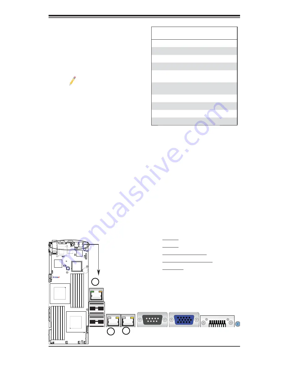
Ethernet Ports

Two Ethernet ports are located next to 

the USB 0/1 on the IO Backplane. In 

addition, an IPMI Dedicated LAN is lo-

cated above the USB ports 0/1. These 

ports accept RJ45 type cables. 

Note

s: 

1. The IPMI Dedicated LAN 

is for the X8DTT-F/-IBXF/-

IBQF only. 

2. Please refer to the LED 

Indicator Section for LAN 

LED information.

LAN Ports

Pin Defi nition

Pin#   Defi nition

1

P2V5SB

10

SGND

2

TD0+

11

Act LED

3

TD0-

12

P3V3SB

4

TD1+

13

Link 100 LED 
(Yellow, +3V3SB)

5

TD1-

14

Link 1000 LED 
(Yellow, +3V3SB)

6

TD2+

15

Ground

7

TD2-

16

Ground

8

TD3+

17

Ground

9

TD3-

88

Ground

(NC: No Connection)

X8DTT Series

Rev. 2.0

1

2

3

1. LAN1

2. LAN2

3. IPMI dedicated LAN

(For the X8DTT-F/-IBXF/-

IBQF only)

Summary of Contents for X8DTT

Page 1: ...X8DTT X8DTT F X8DTT IBX X8DTT IBXF X8DTT IBQ X8DTT IBQF USER S MANUAL Revision 1 0b...

Page 2: ...UCH DAMAGES IN PARTICULAR SUPERMICRO SHALL NOT HAVE LIABILITY FOR ANY HARDWARE SOFTWARE OR DATA STORED OR USED WITH THE PRODUCT INCLUDING THE COSTS OF REPAIRING REPLACING INTEGRATING INSTALLING OR REC...

Page 3: ...high end servers and intensive applications Please refer to our web site http www supermicro com products for updates on supported processors This product is intended to be installed and serviced by p...

Page 4: ...the following symbols for proper installation and to prevent product damage or bodily injury Warning Important information given to ensure proper system installation or to prevent damage to the compon...

Page 5: ...Super Micro Computer B V Het Sterrenbeeld 28 5215 ML s Hertogenbosch The Netherlands Tel 31 0 73 6400390 Fax 31 0 73 6416525 Email sales supermicro nl General Information support supermicro nl Technic...

Page 6: ...llation Instructions 2 5 2 4 Processor and Heatsink Installation 2 6 Installing a CPU Heatsink 2 8 2 5 Memory Installation 2 10 2 6 Control Panel Connectors IO Ports 2 15 Back Panel Connectors IO Port...

Page 7: ...UID_OW Overwriting 2 35 BMC Enable For X8DTT F IBXF IBQF only 2 36 2 9 Onboard Indicators 2 37 GLAN LEDs 2 37 BMC Heartbeat LED X8DTT F IBX F IBQF 2 37 InfiniBand LED Indicators LEB1 LEB2 X8DTT IBX IB...

Page 8: ...anual 4 5 Boot Configuration 4 26 4 6 Exit Options 4 27 Appendix A BIOS Error Beep Codes A 1 BIOS Error Beep Codes A 1 Appendix B Software Installation Instructions B 1 Installing Software Programs B...

Page 9: ...ed with your motherboard If anything listed here is damaged or missing contact your retailer The following items are included in the bulk package One 1 Supermicro Mainboard Two 2 Serial ATA cables CBL...

Page 10: ...he manual The motherboard you ve received may or may not look exactly the same as the graphics shown in the manual X8DTT F IBX IBXF IBQ IBQF Motherboard Image Model Variations Differences between X8DT...

Page 11: ...setting Warning To avoid possible system overheating please be sure to provide adequate airflow to your system JF1 LE4 SW1 J18 JWR2 JWR1 FAN2 FAN1 FAN4 JP10 JWOL1 J19 JWD1 J119 JPL1 JPG1 JPEN1 JBT1 LE...

Page 12: ...A4 P1 DIMM3B P2 DIMM1A P1 DIMM3A P2 DIMM1B P1 DIMM2B P2 DIMM2A P1 DIMM2A P2 DIMM2B P1 DIMM1B P2DIMM3A P2DIMM3B VGA COM1 LAN2 LAN1 USB0 1 IPMI_LAN PCI E 2 0 GEN2 X16 CPU2 I SATA3 I SATA1 IPMB USB2 3 I...

Page 13: ...nel Connector JNMI1 NMI Non Maskable Interrupt Header JP10 Onboard 4 pin Power Connector JPSK1 Internal Speaker Buzzer Header JTPM1 Trusted Platform Module Header JWR1 JWR2 12V 20 pin Power Connector...

Page 14: ...CI E x16 Gen 2 0 slot BIOS 32 Mb AMI SPI Flash ROM ACPI 1 0 2 0 3 0 Plug and Play PnP and USB Keyboard support PC Health Monitoring Onboard voltage monitors for CPU1 VCore CPU2 VCore 5Vin 12Vcc V VP1...

Page 15: ...X8DTT F IBXF IBQF Intel 82576 Dual LAN Gigabit Ethernet Controller supports dual Giga bit LAN ports Onboard PHY Chip supports IPMI dedicated LAN X8DTT F IBXF IBQF One COM port InfiniBand Connector Up...

Page 16: ...or OEM only PROCESSOR 0 PROCESSOR 1 1 1 1 2 DDR3 DIMM 2 2 DDR3 DIMM 1 1 1 DDR3 DIMM 2 2 2 DDR3 DIMM C C A A B B D D E E F F Port1 Port0 Ports Ports 3 4 7 8 9 10 PCI E x16 Slot ICH10R Ports 2 1 Kawela...

Page 17: ...differential lanes for transmission and receiving in addition to a differential forwarded clock A full width QPI link pair provides 84 signals Each processor supports two QuickPath links one going to...

Page 18: ...ine the sensitivity of the voltage monitor Fan Status Monitor with Firmware Control The PC health monitor can check the RPM status of the cooling fans The onboard CPU and chassis fans are controlled b...

Page 19: ...nto a suspend state the chassis power LED will start blinking to indicate that the CPU is in suspend mode When the user presses any key the CPU will wake up and the LED will automatically stop blinkin...

Page 20: ...oid problems caused by power surges Note The X8DTT F IBX IBXF IBQ IBQF supports proprietary power connectors Please refer to Page 2 21 for detailed information on power supply for the motherboard 1 7...

Page 21: ...omponents Read this section in its entirety before installing or configuring components in the Supermicro chassis Battery Handling Warning There is a danger of explosion if the battery is replaced inc...

Page 22: ...e explosi n si la bater a se reemplaza de manera incorrecta Re emplazar la bater a exclusivamente con el mismo tipo o el equivalente recomen dado por el fabricante Desechar las bater as gastadas seg n...

Page 23: ...dieses Produkts sollte gem allen Bestimmungen und Gesetzen des Landes erfolgen Advertencia Al deshacerse por completo de este producto debe seguir todas las leyes y regla mentos nacionales Attention L...

Page 24: ...ts When handling chips or modules avoid touching their pins Put the motherboard and peripherals back into their antistatic bags when not in use For grounding purposes make sure your computer chassis p...

Page 25: ...assis 2 Locate the mounting holes on the mother board Refer to the layout above for mount ing hole locations 3 Locate the matching mounting holes on the chassis Align the mounting holes on the motherb...

Page 26: ...tsink fans 3 When purchasing a 5500 5600 Series processor or when receiving a moth erboard with a 5500 5600 Series processor pre installed make sure that the CPU plastic cap is in place and none of th...

Page 27: ...f the socket or its pins to avoid damaging the CPU or the socket 7 With the CPU inside the socket in spect the four corners of the CPU to make sure that the CPU is properly installed 8 Once the CPU is...

Page 28: ...dy been ap plied Screw 1 Screw 2 Install Screw 1 2 Place the heatsink on top of the CPU so that the four mounting holes are aligned with those on the retention mechanism 3 Install two diagonal screws...

Page 29: ...remove the heatsink screws from the motherboard in the se quence as show in the picture on the right 4 Hold the heatsink as shown in the picture on the right and gently wriggle the heatsink to loosen...

Page 30: ...ion to the notch along the bottom of the module to prevent inserting the DIMM module incor rectly 3 Gently press down on the DIMM module until it snaps into place in the slot Repeat for all modules Me...

Page 31: ...s in MHz Ranks per DIMM any combination SR Single Rank DR Dual Rank QR Quad Rank 2 1 Reg DDR3 ECC 800 1066 1333 SR or DR 2 1 Reg DDR3 ECC 800 1066 Note 1 QR 2 2 Reg DDR3 ECC 800 1066 Note 1 Mixing SR...

Page 32: ...Type Unb Unbuffered Speeds in MHz Ranks per DIMM any combination SR Single Rank DR Dual Rank QR Quad Rank 2 1 Unb DDR3 ECC Non ECC 800 1066 1333 SR or DR 2 2 Unb DDR3 ECC Non ECC 800 1066 1333 Mixing...

Page 33: ...more than 4 GB of memory Note 2 Due to memory allocation to system devices the amount of mem ory that remains available for operational use will be reduced when 4 GB of RAM is used The reduction in me...

Page 34: ...ce Pay attention to the alignment notch at the bottom Installing and Removing DIMMs To Remove Use your thumbs to gently push the release tabs near both ends of the module This should release it from t...

Page 35: ...ion See the picture below for the colors and locations of the various I O ports Back Panel Connectors IO Ports 1 2 3 4 5 6 7 8 9 X8DTT Series Rev 2 0 Back Panel Connectors 1 USB 0 2 USB 1 3 IPMI_Dedic...

Page 36: ...s headers to use USB connections USB cables are not included See the tables on the right for pin definitions Back Panel USB 0 1 Pin Definitions Pin Definition Pin Definition 1 5V 5 5V 2 USB_PN1 6 USB_...

Page 37: ...ed LAN is for the X8DTT F IBXF IBQF only 2 Please refer to the LED Indicator Section for LAN LED information LAN Ports Pin Definition Pin Definition 1 P2V5SB 10 SGND 2 TD0 11 Act LED 3 TD0 12 P3V3SB 4...

Page 38: ...t Pin Definitions COM1 Pin Definition Pin Definition 1 CDC 6 DSR 2 RXD 7 RTS 3 TXD 8 CTS 4 DTR 9 RI 5 Ground 10 NC Video Connector A Video VGA connector is located next to the COM Port on the IO backp...

Page 39: ...3 3 V Power supply receiver 11 2 wire serial interface clock 12 2 wire serial interface data 13 Ground 14 Receiver Non Inverted Data Output 15 Receiver Inverted Data Output 16 Ground 17 Receiver Non...

Page 40: ...tch on the front panel or on the back panel both Rear UID LED and Front Panel UID LED Indicators will be turned on Press the UID switch again to turn off both LED Indicators These UID Indica tors prov...

Page 41: ...he figure below for the descriptions of the various control panel buttons and LED indicators Refer to the following section for descriptions and pin definitions JF1 Header Pins Power Button OH Fan Fai...

Page 42: ...in Definition 15 3 3V SB 16 PWR LED Front Control Panel Pin Definitions A PWR LED B HDD LED FP UID Switch LED A B X8DTT Series Rev 2 0 HDD FP UID Switch The HDD UID Switch connections are located on p...

Page 43: ...rt 1 are located on pins 11 and 12 of JF1 Attach a NIC LED cable to display LAN Port1 connections and activities Refer to the table on the right for pin definitions GLAN1 LED Pin Definitions JF1 Pin D...

Page 44: ...7 works as the UID LED indicator for the front panel UID switch located on pins 13 14 of JF1 When Jumper J_UID_OW is set to off default the Red LED takes precedence over the Blue LED See Page 2 31 for...

Page 45: ...the system This button can also be configured to function as a suspend button with a setting in the BIOS see Chapter 4 To turn off the power when set to suspend mode press the button for at least 4 s...

Page 46: ...e connector can be used for input power supply to the motherboard at a time For proper use of these proprietary PWR Con nectors please customize your PWR cables based on Supermicro PWR Connector Pin O...

Page 47: ...and Connector 4 pin PWR North Bridge South Bridge JTPM1 LE1 Rev 2 0 JBMC1 JPB A Required Connection D 4 pin Auxiliary Power Connector In addition to two 20 pin power connectors a 4 pin 12V PWR supply...

Page 48: ...otherboard All these 4 pin fans headers are backward compatible with the traditional 3 pin fans However fan speed control is available for 4 pin fans only The fan speeds are controlled by Thermal Mana...

Page 49: ...10R Nuvoton WPCM450 PHY InfiniBand CTRL LAN CTRL InfiniBand Connector 4 pin PWR North Bridge South Bridge JTPM1 LE1 Rev 2 0 JBMC1 JPB B A A NMI Header B Internal Speaker Internal Buzzer The Internal...

Page 50: ...Bridge JTPM1 LE1 Rev 2 0 JBMC1 JPB A B C A Wake On LAN B T SGPIO0 C T SBPIO1 Wake On LAN The Wake On LAN header is located at JWOL1 on the motherboard You must also have a LAN card with a Wake On LAN...

Page 51: ...ntel ICH 10R Nuvoton WPCM450 PHY InfiniBand CTRL LAN CTRL InfiniBand Connector 4 pin PWR North Bridge South Bridge JTPM1 LE1 Rev 2 0 JBMC1 JPB A B A PWR SMB B IPMB SMB IPMB I2 C SMB For X8DTT F IBXF I...

Page 52: ...Bridge South Bridge JTPM1 LE1 Rev 2 0 JBMC1 JPB 2 8 Jumper Settings Explanation of Jumpers To modify the operation of the motherboard jumpers can be used to choose between optional settings Jumpers cr...

Page 53: ...onsists of contact pads to prevent the accidental clearing of CMOS To clear CMOS use a metal object such as a small screwdriver to touch both pads at the same time to short the connection Always remov...

Page 54: ...JBMC1 JPB A A PWR Setting Select B VGA Enable B Power Setting Select Jumper Settings Jumper Definition Pins 1 2 Onboard PWR setting Pins 2 3 Hot Swap support Power Setting Select JPEN1 allows you to c...

Page 55: ...Fail LED and the Blue UID_ LED function independently Red LED does not overwrite the Blue LED The Red LED has no effects on the Blue_UID LED Red LED On Blue LED On Off Red LED Off Blue LED On Off J_UI...

Page 56: ...2 FAN1 FAN4 JP10 JWOL1 J19 JWD1 J119 JPL1 JPG1 JPEN1 JBT1 LEB1 LEB2 LE2 JBAT1 JNMI1 JSPK1 J_UID_OW T SGPIO0 I SATA5 I SATA4 P1 DIMM3B P2 DIMM1A P1 DIMM3A P2 DIMM1B P1 DIMM2B P2 DIMM2A P1 DIMM2A P2 DIM...

Page 57: ...he X8DTT F IBXF IBXQF Each Gigabit Ethernet LAN port has two LEDs The yellow LED indicates activity while the Link LED may be green amber or off to indicate the speed of the connection See the tables...

Page 58: ...the system power is on Be sure to turn off the system and unplug the power cord before removing or installing components See the tables at right for more information Onboard PWR LED Indicator Setting...

Page 59: ...iBand Connector 4 pin PWR North Bridge South Bridge JTPM1 LE1 Rev 2 0 JBMC1 JPB Serial ATA Pin Definitions Pin Definition 1 Ground 2 TX_P 3 TX_N 4 Ground 5 RX_N 6 RX_P 7 Ground C G F E D A I SATA0 B I...

Page 60: ...2 40 X8DTT F IBX IBXF IBQ IBQF User s Manual Notes...

Page 61: ...erboard and chassis 2 Disconnect all ribbon wire cables from the motherboard including those for the keyboard and mouse 3 Remove all add on cards 4 Install CPU 1 first making sure it is fully seated a...

Page 62: ...repairs Memory Errors When a No_Memory_Beep_Code is issued by the system check the following 1 Make sure that the DIMM modules are properly and fully installed 2 Check if different speeds of DIMMs hav...

Page 63: ...information when contacting Supermicro for technical support Motherboard model and PCB revision number BIOS release date version this can be seen on the initial display when your system first boots u...

Page 64: ...r a few minutes Warning Do not shut down or reset the system while updating the BIOS to prevent possible system boot failure Note The SPI BIOS chip used on this motherboard cannot be removed Send your...

Page 65: ...ions cannot be configured Options in blue can be configured by the user The right frame displays the key legend Above the key legend is an area reserved for a text message When an option is selected i...

Page 66: ...ages arising from a BIOS update If you have to update the BIOS do not shut down or reset the system while the BIOS is updating This is to avoid possible boot failure 4 2 Main Setup When you first ente...

Page 67: ...sed in your system CPU Type This item displays the type of CPU used in the motherboard Speed This item displays the speed of the CPU detected by the BIOS Physical Count This item displays the number o...

Page 68: ...een options to be modified between POST mes sages or the OEM logo Select Disabled to display the POST messages Select Enabled to display the OEM logo instead of the normal POST messages The op tions a...

Page 69: ...onds or longer The options are Instant_Off and 4_Second_Override Restore on AC Power Loss Use this feature to set the power state after a power outage Select Power Off for the system power to remain o...

Page 70: ...mputer The options are Enabled and Disabled Note If there is any change to this setting you will need to power off and restart the system for the change to take effect Please refer to Intel s web site...

Page 71: ...mote C3 C6 or C7 requests to C1 based on un core auto demote information The options are Disabled and Enabled C3 Auto Demotion When enabled the CPU will conditionally demote C6 or C7 requests to C3 ba...

Page 72: ...is used to trigger fail over The spare memory is put online and used as active memory in place of the failed memory Demand Scrubbing A memory error correction scheme where the Processor writes correc...

Page 73: ...ters above or below sea level the system is located The options are Sea Level or Below 1 300 301 600 601 900 901 1200 1201 1500 1501 1800 1801 2100 2101 2400 2401 2700 2701 3000 DIMM Pitch This is the...

Page 74: ...de for the desired setting The options are 256 MB and 128MB SouthBridge Configuration This feature allows the user to configure the settings for the Intel ICH South Bridge chipset USB Functions This f...

Page 75: ...the item SATA AHCI will be available ICH RAID Code Base This feature is available when the option RAID is selected Select Intel to enable Intel s SATA RAID firmware to configure Intel s SATA RAID sett...

Page 76: ...de boosts the IDE drive performance by increasing the amount of data transferred Only 512 bytes of data can be transferred per interrupt if Block Mode is not used Block Mode allows transfers of up to...

Page 77: ...a transfer rate of 16 6 MB s Select UDMA0 to allow the BIOS to use Ultra DMA mode 0 It has a data transfer rate of 16 6 MB s It has the same transfer rate as PIO mode 4 and Multi Word DMA mode 2 Selec...

Page 78: ...OS to configure all devices in the system PCI Latency Timer This feature sets the latency Timer of each PCI device installed on a PCI bus Select 64 to set the PCI latency to 64 PCI clock cycles The op...

Page 79: ...s feature allows the user to set the flow control for Console Redirection The options are None Hardware and Software Redirection After BIOS POST Select Disabled to turn off Console Redirection after P...

Page 80: ...ding the LED and the buzzer to be triggered when the CPU temperature reaches about 5oC above the threshold temperature as predefined by the CPU manufacturer to give the CPU and system fans additional...

Page 81: ...entilation for blockage High The processor is running hot This is a caution level since the CPU s Tem perature Tolerance has been reached or has been exceeded and may activate an overheat alarm User i...

Page 82: ...ptions are Enabled and Disabled Headless Mode This feature is used to enable system to function without a keyboard monitor or mouse attached The options are Enabled and Disabled High Performance Event...

Page 83: ...hardware This is an informational feature which returns the status code of the BMC micro controller View BMC System Event Log This feature displays the BMC System Event Log SEL It shows the total numb...

Page 84: ...ent Log Clear BMC System Log Select OK and press the Enter key to clear the BMC system log Select Cancel to keep the BMC System log The options are OK and Cancel Warning Any cleared information is unr...

Page 85: ...annel Number Status This feature returns the channel status for the Channel Number selected above Channel Number is OK or Wrong Channel Number IP Address Configuration Enter the IP address for this ma...

Page 86: ...ted by dots should not exceed 255 as shown in the screen below Parameter Selector Use this feature to select the parameter of your Mac Address configuration Mac Address The BIOS will automatically ent...

Page 87: ...er Cycle OEM Action Diagnostic Interface Alert Startup Delay This feature inserts a delay during startup for PEF alerts The options are Enabled and Disabled PEF Alert Startup Delay This sets the pre d...

Page 88: ...are Disabled Reset System Power Down Power Cycle BMC Watch Dog TimeOut Min Sec This option appears if BMC Watch Dog Timer Action above is enabled This is a timed delay in minutes or seconds before a s...

Page 89: ...user password has not been used Change Supervisor Password Select this feature and press Enter to access the submenu and then type in a new Supervisor Password User Access Level Available when Supervi...

Page 90: ...led the AMI BOIS displays a warning when any program or virus is sues a Disk Format command or attempts to write to the boot sector of the hard disk drive The options are Enabled and Disabled 4 5 Boot...

Page 91: ...rive SATA XXXXXXXXX Removable Drives This feature allows the user to specify the boot sequence from available Removable Drives The settings are 1st boot device 2nd boot device and Disabled 1st Drive U...

Page 92: ...nges and Exit from the Exit menu and press Enter Discard Changes Select this option and press Enter to discard all the changes and return to the AMI BIOS Utility Program Load Optimal Defaults To set t...

Page 93: ...low the system to continue the boot up procedure If a fatal error occurs you should consult with your system manufacturer for possible repairs A 1 BIOS Error Beep Codes BIOS Error Beep Codes Beep Code...

Page 94: ...A 2 X8DTT F IBX IBXF IBQ IBQF User s Manual Notes...

Page 95: ...er diskette from booting into a Driver CD please set the SATA Configuration to Compatible Mode and configure SATA as IDE in the BIOS Setup After making the driver diskette be sure to change the SATA s...

Page 96: ...ctor III displays crucial system information such as CPU temperature system voltages and fan status See the Figure below for a display of the Supero Doctor III interface Note 1 The default user name a...

Page 97: ...te Control Note SD III Software Revision 1 0 can be downloaded from our Web site at ftp ftp supermicro com utility Super_Doctor_III You can also download SDIII User s Guide at http www supermicro com...

Page 98: ...B 4 X8DTT F IBX IBXF IBQ IBQF User s Manual Notes...

Page 99: ...expected to result in significant injury or loss of life or catastrophic property damage Accordingly Supermicro disclaims any and all liability and should buyer use or sell such products for use in su...

Reviews: