background image

2-34

 X7DB8/X7DBE 

User's 

Manual

®

JLAN1

S

UPER     X7DB8/E

A

B

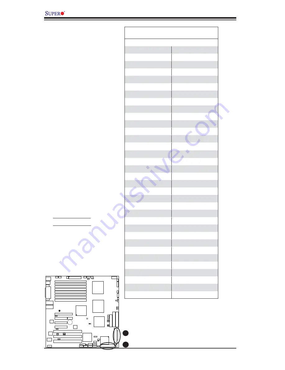
A. SCSI Channel A

B. SCSI Channel B

Ultra 320 SCSI 
Connectors (*X7DB8 
only)   


There are two SCSI connectors 

on the motherboard. SCSI 

Channel A is located at JA1, 

and SCSI Channel B is located 

at  A2. Refer to the table below 

for the pin defi nitions of the 

Ultra 320 SCSI connectors 

located at JA1 and JA2.

Ultra320 SCSI Drive Connector

Pin Defi nitions

Pin#     Defi nition                  Pin #      Defi nition

1

+DB (12)

35

-DB (12)

2

+DB (13)

36

-DB (13)

3

+DB (14)

37

-DB (14)

4

+DB (15)

38

-DB (15)

5

+DB (P1)

39

-DB (P1)

6

+DB (0)

40

-DB (0)

7

+DB (1)

41

-DB (1)

8

+DB (2)

42

-DB (2)

9

+DB (3)

43

-DB (3)

10

+DB (4)

44

-DB (4)

11

+DB (5)

45

-DB (5)

12

+DB (6)

46

-DB (6)

13

+DB (7)

47

-DB (7)

14

+DB (P)

48

-DB (P)

15

Ground

49

Ground

16

DIFFSENS

50

Ground

17

TERMPWR

51

TERMPWR

18

TERMPWR

52

TERMPWR

19

Reserved

53

Reserved

20

Ground

54

Ground

21

+ATN

55

-ATN

22

Ground

56

Ground

23

+BSY

57

-BSY

24

+ACK

58

-ACK

25

+RST

59

-RST

26

+MSG

60

-MSG

27

+SEL

61

-SEL

28

+C/D

62

-C/D

29

+REQ

63

-REQ

30

+I/O

64

-I/O

31

+DB (8)

65

-DB (8)

32

+DB (9)

66

-DB (9)

33

+DB (10)

67

-DB (10)

34

+DB (11)

68

-DB (11)

Summary of Contents for X7DB8

Page 1: ...SUPER X7DB8 X7DBE USER S MANUAL Revision 1 1a...

Page 2: ...cro s total liability for all claims will not exceed the price paid for the hardware product FCC Statement This equipment has been tested and found to comply with the limits for a Class A digital devi...

Page 3: ...nterprise server workstation environments This product is intended to be professionally installed Manual Organization Chapter 1 describes the features speci cations and performance of the mainboard an...

Page 4: ...rom AC Power Loss 1 10 1 4 PC Health Monitoring 1 10 1 5 ACPI Features 1 11 1 6 Power Supply 1 12 1 7 Super I O 1 13 Chapter 2 Installation 2 1 Static Sensitive Devices 2 1 Precautions 2 1 Unpacking 2...

Page 5: ...Alarm Reset 2 20 Overheat LED Fan Fail 2 21 SMB Connector 2 21 SMB Power Connector 2 22 VGA Connector 2 22 Compact Flash Card PWR Connector 2 23 SGPIO Headers 2 23 2 6 Jumper Settings 2 24 Explanatio...

Page 6: ...guration 3 1 3 2 Technical Support Procedures 3 2 3 3 Frequently Asked Questions 3 3 3 4 Returning Merchandise for Service 3 3 Chapter 4 BIOS 4 1 Introduction 4 1 4 2 Running Setup 4 2 4 3 Main BIOS...

Page 7: ...ave all been included with your motherboard If anything listed here is damaged or missing contact your retailer All the following items are included in the Retail Box One 1 Supermicro Mainboard One 1...

Page 8: ...Super Micro Computer B V Het Sterrenbeeld 28 5215 ML s Hertogenbosch The Netherlands Tel 31 0 73 6400390 Fax 31 0 73 6416525 Email sales supermicro nl General Information support supermicro nl Techni...

Page 9: ...Note The drawings and pictures shown in this manual were based on the latest PCB Revision available at the time of publishing of the manual The motherboard you ve received may or may not look exactly...

Page 10: ...X 100 MHz ZC R P C I X 133 MHz J WD B attery VGA C T R L PCI E xp x8 North B ridge VGA C OM1 US B 0 1 K B Mous e F an6 F an5 ATX PWR 4 Pin PWR J3P P arrallel P ort 24 Pin J P G 1 S CS I CTR L C P U1 C...

Page 11: ...4B Memory FBD DDRII Slots FAN 1 8 Fans 1 8 CPU Fans Chassis Fans Floppy J22 Floppy Disk Drive Connector FP CTRL JF1 Front Control Panel Connector GLAN 1 2 JLAN1 2 G bit Ethernet Ports IDE1 IDE2 Note...

Page 12: ...two slots at x8 4GB sec one slot x4 2GB sec Three 64 bit PCI X slots two PCI X 133 slots one PCI X 100 w ZCR slot BIOS 8 Mb Phoenix Flash ROM DMI 2 3 PCI 2 2 ACPI 1 0 Plug and Play PnP PC Health Monit...

Page 13: ...g one IDE the blue slot and one Compact Flash card the blue slot Two SGPIO Serial General Purpose Input Output headers One oppy port interface Two COM ports 1 header 1 port One EPP ECP Parallel Port P...

Page 14: ...XPx8 PC I 32 33 S AT A 0 5 x8 PCI E x4 GB LAN FWH RJ45 RJ45 LPC CO M SIO W83627 US B S EPC ATA 100 KB VGA KUM ERAN US B 2 0 3 0Gb S VRM 6307 VRM 6307 PROCESSOR 1 667 1067 1333 PARALLEL PORT 6 HF 4 PCI...

Page 15: ...ystem PXH The 5000P Blackford MCH chipset is designed for symmetric multiprocessing across two independent front side bus interfaces Each front side bus uses a 64 bit wide 1333 MHz data bus that trans...

Page 16: ...ntinuously Once a voltage becomes unstable a warning is given or an error message is sent to the screen Users can adjust the voltage thresholds to de ne the sensitivity of the voltage monitor Fan Stat...

Page 17: ...ation and Power Interface The ACPI speci ca tion de nes a exible and abstract hardware interface that provides a standard way to integrate power management features throughout a PC system including it...

Page 18: ...ity of a management application to remotely power up a computer that is powered off Remote PC setup up dates and asset tracking can occur after hours and on weekends so that daily LAN traf c is kept t...

Page 19: ...nterface control logic and interrupt and DMA logic The wide range of functions integrated onto the Super I O greatly reduces the number of components required for interfacing with oppy disk drives The...

Page 20: ...1 14 X7DB8 X7DBE User s Manual Notes...

Page 21: ...not touch its components peripheral chips memory modules or gold contacts When handling chips or modules avoid touching their pins Put the motherboard and peripherals back into their antistatic bags w...

Page 22: ...install the CPU heatsink 2 Intel s boxed Xeon CPU package contains the CPU fan and heatsink assembly If you buy a CPU separately make sure that you use only Intel certi ed multi di rectional heatsink...

Page 23: ...the socket or move the CPU horizontally or vertically Do not rub the CPU against the surface or against any pins of the socket to avoid damage to the CPU or the socket 7 With the CPU inside the socket...

Page 24: ...etention mechanism 3 Screw in two diagonal screws ie the 1 and the 2 screws until just snug do not fully tighten the screws to avoid possible damage to the CPU 4 Finish the installation by fully tight...

Page 25: ...precautionary measures to prevent damage done to these components when you install the motherboard to the chassis 1 Unscrew and remove the heatsink screws from the motherboard in the sequence as show...

Page 26: ...of memory modules of the same size and same type will result in Interleaved Memory which will increase memory performance Note 1 Due to OS limitations some operating systems may not show more than 4...

Page 27: ...from the slot II DDR2 FBD DDR2 FBD Slot Possible System Memory Allocation Availability System Device Size Physical Memory Remaining Available 4 GB Total System Memory Firmware Hub ash memory System BI...

Page 28: ...the colors and locations of the various I O ports A Back Panel Connectors IO Ports Figure 2 3 Back Panel I O Port Locations and De nitions Back Panel Connectors 1 Keyboard Purple 2 PS 2 Mouse Green 3...

Page 29: ...rs are designed speci cally for use with Supermicro server chassis See Figure 2 4 for the descriptions of the various control panel buttons and LED indicators Refer to the following section for descri...

Page 30: ...nel Pin De nitions A NMI B PWR LED A B GLAN1 JLAN1 SUPER X7DB8 E GLAN2 Fan1 8 pin PWR FP Ctrl SPK PW LED JOH1 Fan3 IDE1 Floppy BIOS 320 SCSI Channel A Fan4 SATA1 SATA0 USB2 3 SMB PCI X 100 MHz ZCR PCI...

Page 31: ...WOL DA1 SI O JP1 LAN CTRL J27 J28 SGPIO1 SGPIO2 SMBPS CTRL J7 Power Button OH Fan Fail LED 1 NIC1 LED Reset Button 2 HDD LED Power LED Reset PWR Vcc Vcc Vcc Vcc Ground Ground 19 20 Vcc X Ground NMI X...

Page 32: ...ing Fan Fail PWR Fail LED Pin De nitions JF1 Pin De nition 5 Vcc 6 Ground A B A OH Fan Fail LED B PWR Supply Fail GLAN1 JLAN1 SUPER X7DB8 E GLAN2 Fan1 8 pin PWR FP Ctrl SPK PW LED JOH1 Fan3 IDE1 Flop...

Page 33: ...JP1 LAN CTRL J27 J28 SGPIO1 SGPIO2 SMBPS CTRL J7 Power Button OH Fan Fail LED 1 NIC1 LED Reset Button 2 HDD LED Power LED Reset PWR Vcc Vcc Vcc Vcc Ground Ground 19 20 Vcc X Ground NMI X Vcc PWR Fail...

Page 34: ...in main power sup ply connector JPW1 and an 8 pin CPU PWR connector JPW3 on the motherboard These power connec tors meet the SSI EPS 12V speci ca tion The 4 pin 12V PWR supply is required to provide a...

Page 35: ...JCOM2 DA2 WOL DA1 SI O JP1 LAN CTRL J27 J28 SGPIO1 SGPIO2 SMBPS CTRL J7 Universal Serial Bus USB There are ve USB 2 0 Universal Se rial Bus ports headers on the moth erboard Two of them are Back Panel...

Page 36: ...7 J28 SGPIO1 SGPIO2 SMBPS CTRL J7 Fan Headers The X7DB8 X7DBE has eight chassis system fan headers Fan1 to Fan8 and two CPU Fans Fans 7 8 Note all these fans are 4 pin fans However Pins 1 3 of the fan...

Page 37: ...2 DIMM 3A Bank 3 DIMM 3B Bank 3 DIMM 4A Bank 4 DIMM 4B Bank 4 JBT1 USB4 JWOR JCOM2 DA2 WOL DA1 SI O JP1 LAN CTRL J27 J28 SGPIO1 SGPIO2 SMBPS CTRL J7 ATX PS 2 Keyboard and PS 2 Mouse Ports The ATX PS...

Page 38: ...Bank 2 DIMM 2B Bank 2 DIMM 3A Bank 3 DIMM 3B Bank 3 DIMM 4A Bank 4 DIMM 4B Bank 4 JBT1 USB4 JWOR JCOM2 DA2 WOL DA1 SI O JP1 LAN CTRL J27 J28 SGPIO1 SGPIO2 SMBPS CTRL J7 Wake On Ring The Wake On Ring h...

Page 39: ...ot7 DIMM 1B Bank 1 DIMM 2A Bank 2 DIMM 2B Bank 2 DIMM 3A Bank 3 DIMM 3B Bank 3 DIMM 4A Bank 4 DIMM 4B Bank 4 JBT1 USB4 JWOR JCOM2 DA2 WOL DA1 SI O JP1 LAN CTRL J27 J28 SGPIO1 SGPIO2 SMBPS CTRL J7 Powe...

Page 40: ...O JP1 LAN CTRL J27 J28 SGPIO1 SGPIO2 SMBPS CTRL J7 Power Fault PWR Supply Failure Connect a cable from your power supply to the Power Fail PSF header to provide warnings of power supply failure This w...

Page 41: ...x8 SEPC SIMLPIPMI Slot7 DIMM 1B Bank 1 DIMM 2A Bank 2 DIMM 2B Bank 2 DIMM 3A Bank 3 DIMM 3B Bank 3 DIMM 4A Bank 4 DIMM 4B Bank 4 JBT1 USB4 JWOR JCOM2 DA2 WOL DA1 SI O JP1 LAN CTRL J27 J28 SGPIO1 SGPIO...

Page 42: ...lot1 Slot2 Slot3 PCI X 133 MHz Slot4 JPL1 JPL2 Slot5 PCI Exp x4 Slot6 PCI Exp x8 SEPC SIMLPIPMI Slot7 DIMM 1B Bank 1 DIMM 2A Bank 2 DIMM 2B Bank 2 DIMM 3A Bank 3 DIMM 3B Bank 3 DIMM 4A Bank 4 DIMM 4B...

Page 43: ...OR JCOM2 DA2 WOL DA1 SI O JP1 LAN CTRL J27 J28 SGPIO1 SGPIO2 SMBPS CTRL J7 A A Compact Flash PWR B SGPIO1 B SGPIO2 Compact Flash Card PWR Connector A Compact Flash Card Power Connector is located at J...

Page 44: ...MM 4B Bank 4 JBT1 USB4 JWOR JCOM2 DA2 WOL DA1 SI O JP1 LAN CTRL J27 J28 SGPIO1 SGPIO2 SMBPS CTRL J7 2 6 Jumper Settings Explanation of Jumpers To modify the operation of the motherboard jumpers can be...

Page 45: ...2 SMBPS CTRL J7 CMOS Clear JBT1 is used to clear CMOS Instead of pins this jumper consists of contact pads to prevent the accidental clearing of CMOS To clear CMOS use a metal object such as a small s...

Page 46: ...2 DA2 WOL DA1 SI O JP1 LAN CTRL J27 J28 SGPIO1 SGPIO2 SMBPS CTRL J7 A A SCSI Enable B SCSI Channel A Termi nation Enable C SCSI Channel B Termi nation Enable SCSI Controller Enable Disable Jumper JPA1...

Page 47: ...k 3 DIMM 4A Bank 4 DIMM 4B Bank 4 JBT1 USB4 JWOR JCOM2 DA2 WOL DA1 SI O JP1 LAN CTRL J27 J28 SGPIO1 SGPIO2 SMBPS CTRL J7 SCSI Enable Disable Jumper Settings Both Jumpers De nition Pins 1 2 Enabled Pin...

Page 48: ...R JCOM2 DA2 WOL DA1 SI O JP1 LAN CTRL J27 J28 SGPIO1 SGPIO2 SMBPS CTRL J7 Compact Flash Master Slave Select ACompact Flash Master Primary Slave Secondary Select Jumper is located at JCF1 Close this ju...

Page 49: ...x8 SEPC SIMLPIPMI Slot7 DIMM 1B Bank 1 DIMM 2A Bank 2 DIMM 2B Bank 2 DIMM 3A Bank 3 DIMM 3B Bank 3 DIMM 4A Bank 4 DIMM 4B Bank 4 JBT1 USB4 JWOR JCOM2 DA2 WOL DA1 SI O JP1 LAN CTRL J27 J28 SGPIO1 SGPIO...

Page 50: ...x8 SEPC SIMLPIPMI Slot7 DIMM 1B Bank 1 DIMM 2A Bank 2 DIMM 2B Bank 2 DIMM 3A Bank 3 DIMM 3B Bank 3 DIMM 4A Bank 4 DIMM 4B Bank 4 JBT1 USB4 JWOR JCOM2 DA2 WOL DA1 SI O JP1 LAN CTRL J27 J28 SGPIO1 SGPIO...

Page 51: ...llel Printer Port Connector The parallel printer port is located on the IO Back Panel See the table on the right for pin de nitions 2 8 Parallel Port Floppy Drive Hard Disk Drive SIMLP IPMI and SCSI C...

Page 52: ...DIMM 3B Bank 3 DIMM 4A Bank 4 DIMM 4B Bank 4 JBT1 USB4 JWOR JCOM2 DA2 WOL DA1 SI O JP1 LAN CTRL J27 J28 SGPIO1 SGPIO2 SMBPS CTRL J7 Floppy Connector The oppy connector is located next to the compact...

Page 53: ...Host Data 6 6 Host Data 9 7 Host Data 5 8 Host Data 10 9 Host Data 4 10 Host Data 11 11 Host Data 3 12 Host Data 12 13 Host Data 2 14 Host Data 13 15 Host Data 1 16 Host Data 14 17 Host Data 0 18 Host...

Page 54: ...ition Pin De nition 1 DB 12 35 DB 12 2 DB 13 36 DB 13 3 DB 14 37 DB 14 4 DB 15 38 DB 15 5 DB P1 39 DB P1 6 DB 0 40 DB 0 7 DB 1 41 DB 1 8 DB 2 42 DB 2 9 DB 3 43 DB 3 10 DB 4 44 DB 4 11 DB 5 45 DB 5 12...

Page 55: ...nd the power LED to the motherboard Check all jumper settings as well No Power 1 Make sure that there are no short circuits between the motherboard and the chassis 2 Make sure that all jumpers are set...

Page 56: ...fully seated in their slots As an in terleaved memory scheme is used you must install two modules at a time beginning with Bank 1 then Bank 2 and so on see Section 2 3 6 Check the position of the 115...

Page 57: ...ith your system Updated BIOS les are located on our web site at http www supermicro com support bios Please check our BIOS warning message and the info on how to update your BIOS on our web site Also...

Page 58: ...all orders that must be mailed when service is complete For faster service RMA authorizations may be requested online http www supermicro com support rma This warranty only covers normal consumer use...

Page 59: ...off a backup battery pro vides power to the CMOS Logic enabling it to retain system parameters When the computer is powered on the computer is con gured with the values stored in the CMOS Logic by the...

Page 60: ...ssing Delete immediately after turning the system on or 2 When the message shown below appears brie y at the bottom of the screen during the POST Power On Self Test press the Delete key to activate th...

Page 61: ...ate Using the arrow keys highlight the month day and year elds and enter the correct data Press the Enter key to save the data BIOS Date This eld displays the date when this version of BIOS was built...

Page 62: ...d options of these items Set the correct con gurations accordingly The items included in the sub menu are Type This item allows you to select the type of IDE hard drive Select Auto to allow the BIOS t...

Page 63: ...ormat Multi Sector Transfers This item allows the user to specify the number of sectors per block to be used in multi sector transfer The options are Disabled 4 Sectors 8 Sectors and 16 Sectors LBA Mo...

Page 64: ...d by the Windows 2000 OS or a later version When the SATA Controller Mode is set to Enhanced the following items will display Serial ATA SATA RAID Enable Select Enable to enable Serial ATA RAID Functi...

Page 65: ...y This display informs you how much extended memory is recognized as being present in the system 4 4 Advanced Setup ChooseAdvancedfromthe PhoenixBIOSSetupUtilitymainmenuwiththearrowkeys You should see...

Page 66: ...stant Off the system will power off immediately as soon as the user hits the power button If set to 4 sec the system will power off when the user presses the power button for 4 seconds or longer The o...

Page 67: ...low data to be cached into the buffer and written into the system memory at the same time Select Write Protect to prevent data from being written into the base memory area of Block 0 512K Select Write...

Page 68: ...g settings for PCI devices Onboard GLAN1 Onboard GLAN2 Gigabit LAN OPROM Con gure Enabling this option provides the capability to boot from GLAN The options are Disabled and Enabled Onboard SCSI OPROM...

Page 69: ...stallation of a new software you might want to change this setting and try again A different OS requires a different Bus Master clock rate Large Disk Access Mode This setting determines how large hard...

Page 70: ...Technology to accelerate the performance of TOE devices Note A TOE device is a specialized dedicated processor that is installed on an add on card or a network card to handle some or all packet proces...

Page 71: ...le if supported by the CPU Set to Enabled to use Thermal Management 2 TM2 which will lower CPU voltage and frequency when the CPU temperature reaches a prede ned overheat threshold Set to Disabled to...

Page 72: ...e platform to run multiple operating systems and applications in independent partitions creating multiple virtual systems in one physical computer The options are Enabled and Disabled Note If there is...

Page 73: ...Port This setting allows you to assign control of the parallel port The options are Enabled user de ned Disabled and Auto BIOS or OS controlled Base I O Address Select the base I O address for the pa...

Page 74: ...capacity It is not a setting View DMI Event Log Highlight this item and press Enter to view the contents of the event log Event Logging This setting allows you to Enable or Disable event logging ECC...

Page 75: ...9 2K 38 4K 57 6K and 115 2K Console Type This item allows you to choose the console redirection type The options are VT100 VT100 8bit PC ANSI 7bit PC ANSI VT100 and VT UTF8 Flow Control This item allo...

Page 76: ...ve When the CPU on die temperature increases the fan speed will also increase and vice versa If the option is set to 3 pin fan the fan speed is controlled by voltage If the op tion is set to 4 pin the...

Page 77: ...by voltage If the op tion is set to 4 pin the fan speed will be controlled by Pulse Width Modulation PWM Select 3 pin if your chassis came with 3 pin fan headers Select 4 pin if your chassis came with...

Page 78: ...peed is controlled by voltage If the op tion is set to 4 pin the fan speed will be controlled by Pulse Width Modulation PWM Select 3 pin if your chassis came with 3 pin fan headers Select 4 pin if you...

Page 79: ...ace The options are Enabled and Disabled Clear System Event Logging Enabling this function to force the BIOS to clear the system event logs during the next cold boot The options are Enabled and Disabl...

Page 80: ...s option when OS Boot Watch Dog is set to Disabled Time Out Option This feature allows the user to determine what action to take in an event of a system boot failure The options are No Action Reset Po...

Page 81: ...Chapter 4 BIOS 4 23 Realtime Sensor Data This feature display information from motherboard sensors such as temperatures fan speeds and voltages of various components...

Page 82: ...password has been entered for the system User Password Is This item indicates if a user password has been entered for the system Clear means such a password has not been used and Set means a user pas...

Page 83: ...n above are bootable devices listed in the sequence of boot order as speci ed The boot functions for the devices included in the candidate list above are currently disabled Use a key or a key to move...

Page 84: ...Exit Discarding Changes Highlight this item and hit Enter to exit the BIOS Setup utility without saving any changes you may have made Load Setup Defaults Highlight this item and hit Enter to load the...

Page 85: ...d Keyboard controller failed test May require replacing keyboard controller Keyboard locked Unlock key switch Unlock the system to proceed Monitor type does not match CMOS Run SETUP Monitor type not c...

Page 86: ...us POST did not complete successfully POST loads default values and offers to run Setup If the failure was caused by incorrect values and they are not corrected the next boot will likely fail On syste...

Page 87: ...ServerBIOS2 test error Cannot generate software NMI Non Maskable Interrupt Fail Safe Timer NMI Failed ServerBIOS2 test error Fail Safe Timer takes too long device Address Con ict Address con ict for s...

Page 88: ...ested One or more I2O Block Storage Devices were excluded from the Setup Boot Menu There was not enough room in the IPL table to display all installed I2O block storage devices Operating system not fo...

Page 89: ...p Optional message displayed during POST Can be turned off in Setup PS 2 Mouse PS 2 mouse identi ed Run the I2O Con guration Utility One or more unclaimed block storage devices have the Con guration R...

Page 90: ...A 6 X7DB8 X7DBE User s Manual Notes...

Page 91: ...error in the top left corner of the screen The following is a list of codes that may be written to port 80h Appendix B BIOS POST Codes POST Code Description 01h IPMI Initialization 02h Verify Real Mod...

Page 92: ...h Shadow system BIOS ROM 3Ah Auto size cache 3Ch Advanced con guration of chipset registers 3Dh Load alternate registers with CMOS values 41h Initialize extended memory for RomPilot optional 42h Initi...

Page 93: ...and IRQs optional 81h Late POST device initialization 82h Detect and install external RS232 ports 83h Con gure non MCD IDE controllers 84h Detect and install external parallel ports 85h Initialize PC...

Page 94: ...prepare to boot operating system B4h 1 One short beep before boot B5h Terminate QuietBoot optional B6h Check password optional B7h Initialize ACPI BIOS and PPM Structures B9h Prepare Boot BAh Initiali...

Page 95: ...type EDh Initialize Memory size EEh Shadow Boot Block EFh System memory test F0h Initialize interrupt vectors F1h Initialize Run Time Clock F2h Initialize video F3h Initialize System Management Manage...

Page 96: ...B 6 X7DB8 X7DBE User s Manual Notes...

Page 97: ...oard Note that the current version of the ESB2 SATA RAID Utility can only support Windows XP 2000 2003 Operating Systems Serial ATA SATA Serial ATA SATA is a physical storage interface that uses a sin...

Page 98: ...RAID Functions Native Mode 1 Press the Del key during system bootup to enter the BIOS Setup Utility Note If it is the rst time powering on the system we recommend you load the Optimized Default Settin...

Page 99: ...appears after Power On Self Test b When you see the above screen press the Ctrl and the I keys simultane ously to have the main menu of the SATA RAID Utility appear Note All graphics and screen shots...

Page 100: ...d press Space to select it A triangle appears to con rm the selection of the drive f Use the Up Arrow Down Arrow keys to select the stripe size ranging from 4 KB to 128 KB for the RAID 0 array and hit...

Page 101: ...select the previous menu c When RAID Level item is highlighted press the Up Arrow Down Arrow keys to select RAID 1 Mirror and hit Enter d When the Capacity item is highlighted enter your RAID volume c...

Page 102: ...Arrow keys to select the stripe size from 4 KB to 128 KB for your RAID 10 and hit Enter The default setting is 64 KB Note For a server please use a lower stripe size and for a multimedia system use a...

Page 103: ...ght a drive and press Space to select it A triangle appears to con rm the selection of the drive f Use the Up Arrow Down Arrow keys to select the stripe size ranging from 4 KB to 128 KB for the RAID 5...

Page 104: ...s when deleting a RAID set a From the main menu select item2 Delete RAID Volume and press Enter b Use the Up Arrow Down Arrow keys to select the RAID set you want to delete and press Del A Warning mes...

Page 105: ...he RAID set drive A Warning message displays d Press Y to reset the drive or type N to go back to the main menu Exiting the Intel Matrix Storage Manager Utility a From the main menu select item4 Exit...

Page 106: ...and press the Enter key e Choose the Intel R ESB2 SATA RAID Controller from the list indicated in the XP 2000 2003 Setup Screen and press the Enter key f Press the Enter key to continue the installat...

Page 107: ...evices It is a serial link which supports SATA Transfer rates up to 3 0 Gbps Because the serial cables used in SATA are thinner than the traditional cables used in Paral lel ATA PATA SATA systems have...

Page 108: ...r key to load the default settings for the BIOS 3 Use the arrow keys to select the Main section in BIOS 4 Scroll down to SATA Control Mode and press the Enter key to select En hanced 5 Scroll down to...

Page 109: ...ications Using the Adaptec RAID Con guration Utility ARC The Adaptec RAID Con guration Utility an embedded BIOS Utility includes the following Array Con guration Utility Use this utility to create con...

Page 110: ...er s Manual Managing Arrays Select this option to view array properties and con gure array settings To select this option using the arrow keys and the enter key select Managing Arrays from the main me...

Page 111: ...isk and may make any data on the disk inaccessible If the drive is used in an array you may not be able to use the array again Do not con gure a disk that is part of a boot array To determine which di...

Page 112: ...you want to con gure and press Insert 3 The drive you ve selected will appear in the Selected Drives Dialog Box on the right as shown below Repeat the same steps until all drives that you want to con...

Page 113: ...endix D Adaptec HostRAID Setup Guidelines D 7 5 Read the warning message as shown in the screen below 6 Make sure that you have selected the correct disk drives to con gure If correct type Y to contin...

Page 114: ...recommended that you con gure devices before you create arrays To create an array 1 From the main menu shown on page D 4 select Create Array 2 Select the disks for the new array and press Insert as t...

Page 115: ...0 or RAID 1 requires two drives 2 Under the item Arrays Label type in a label and press Enter Note The label shall not be more than 15 characters 3 For RAID 0 select the desired stripe size Note Avai...

Page 116: ...izes in a RAID However you can only select a smaller drive as the source or rst drive during a build operation 5 When migrating from single volume to RAID 0 migrating from a larger drive to a smaller...

Page 117: ...d An asterisk will appear next to the bootable array as shown in the picture below Deleting a Bootable Array To delete a bootable array 1 From the Main menu select Manage Arrays 2 From the List of Arr...

Page 118: ...d press Insert and then press Enter 3 Press Yes when the following prompt is displayed Do you want to create spare Yes No The spare you have selected will appear in the Selected drives Menu To delete...

Page 119: ...Arrays and hit Enter as shown on the previous page 2 From the List of Arrays dialog box shown below select the array you want to view and press Enter The Array Properties dialog box appears as shown b...

Page 120: ...build to restore its functionality For a critical array rebuilding operation the optimal drive is the source drive Note 2 If no spare array exists and a hard disk drive fails you need to create a spar...

Page 121: ...to delete and press delete 3 In the Array Properties dialog box select Delete and press Enter The follow ing prompt is displayed Warning Deleting the array will render array unusable Do you want to de...

Page 122: ...format or verify the media of your Serial ATA hard disks To access the disk utilities 1 From the Adaptec RAID Con guration Utility Menu select Disk Utilities as shown above and press Enter The followi...

Page 123: ...at the factory and do not need to be low level formatted again 3 When the screen shown below displays select Format Disk and press Enter The following screen appears 4 Read the warning message when i...

Page 124: ...the screen shown above displays select Verify Disk Media and press Enter 4 A message will display indicating that the selected drive will be scanned for media defects Select Yes and hit Enter to proc...

Page 125: ...aptec HostRAID Setup Guidelines D 19 To Exit Adaptec RAID Con guration Utility 1 Once you have completed RAID array con gurations press ESC to exit The following screen will appear 2 Press Yes to exit...

Page 126: ...he F6 key when the message Press F6 if you need to install a third party SCSI or RAID driver displays h When the Windows OS Setup screen appears press S to specify additional device s i Insert the dri...

Page 127: ...stem before proceeding with the next item on the list The bottom icon with a CD on it allows you to view the entire contents of the CD Appendix E Installing Other Software Programs and Drivers E 1 Ins...

Page 128: ...isplays crucial system information such as CPU temperature system voltages and fan status See the Figure below for a display of the Supero Doctor III interface Note 1 The default user name and passwor...

Page 129: ...I Remote Control Note SD III Software Revision 1 0 can be downloaded from our Web site at ftp ftp supermicro com utility Supero_Doctor_III You can also download SDIII User s Guide at http www supermic...

Page 130: ...E 4 X7DB8 X7DBE User s Manual Notes...

Reviews: