


Chapter 6: Advanced Chassis Setup
6-3
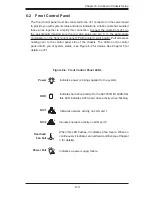
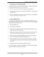
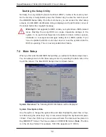
6-2 Front Control Panel
The front control panel must be connected to the JF1 connector on the serverboard
to provide you with system status and alarm indications. A ribbon cable has bundled
these wires together to simplify this connection. Connect the cable from JF1 on
the serverboard (making sure the red wire plugs into pin 1) to the appropriate
comnnector on the front control panel's PCB (printed circuit board). Pull all excess
cabling over to the control panel side of the chassis. The LEDs on the control
panel inform you of system status - see Figure 6-2 for details. See Chapter 5 for
details on JF1.
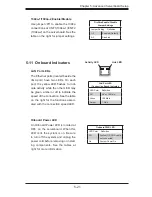
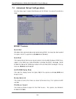
Figure 6-2. Front Control Panel LEDs
Power
NIC1
HDD
Power Fail
Overheat/
Fan Fail
Indicates power is being supplied to the system.
Indicates network activity on LAN port 1.
Indicates hard drive activity. On the SC745TQ-R1400B-SQ,
this LED indicates SATA hard drive activity when
fl
ashing.
Indicates a power supply failure.
When this LED
fl
ashes, it indicates a fan failure. When on
continuously it indicates an overheat condition (see Chapter
3 for details).
NIC2
Indicates network activity on LAN port 2
2
1
Summary of Contents for SuperWorkstation 7046A-HR+
Page 1: ...SuperWorkstation 7046A HR 7046A HR F SUPER USER S MANUAL 1 0a...
Page 5: ...Notes Preface v...
Page 10: ...Notes SuperWorkstation 7046A HR 7046A HR F User s Manual...
Page 16: ...1 6 SuperWorkstation 7046A HR 7046A HR F User s Manual Notes...
Page 30: ...3 4 SuperWorkstation 7046A HR 7046A HR F User s Manual Notes...
Page 72: ...6 12 SuperWorkstation 7046A HR 7046A HR F User s Manual Notes...
Page 104: ...7 32 SuperWorkstation 7046A HR 7046A HR F User s Manual Notes...
Page 106: ...A 2 SuperWorkstation 7046A HR 7046A HR F User s Manual Notes...


