Supero SuperServer 7034L-i User Manual Download Page 102

C-14

S

UPER

S

ERVER 7034L-i User's Manual

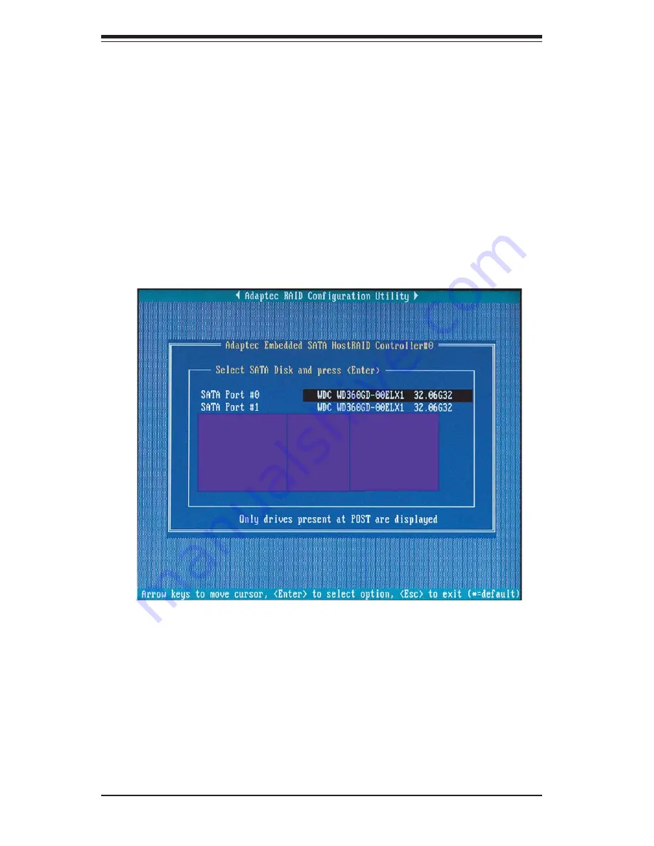
Using the Disk Utilities

The Disk Utilities enable you to format or verify the media of your Serial ATA hard 

disks.

To access the disk utilities:

1. Turn on your computer and press Ctrl+A when prompted to access the ARC 

utility. 

2. From the ARC menu, select Disk Utilities.

3. Select the desired disk and press Enter (as shown below.)

Summary of Contents for SuperServer 7034L-i

Page 1: ...SUPER SUPERSERVER 7034L i USER S MANUAL Revision 1 0...

Page 2: ...PRODUCT OR DOCUMENTATION EVEN IF ADVISED OF THE POSSIBILITY OF SUCH DAMAGES IN PARTICULAR THE VENDOR SHALL NOT HAVE LIABILITY FOR ANY HARDWARE SOFTWARE OR DATA STORED OR USED WITH THE PRODUCT INCLUDI...

Page 3: ...chapter provides a checklist of the main components included with the server and describes the main features of the Super X6DLP EG2 serverboard and the SC733i 450 chassis Chapter 2 Server Installatio...

Page 4: ...adding or removing processors or main memory and when recon guring the serverboard Chapter 6 Advanced Chassis Setup Refer to Chapter 6 for detailed information on the SC733i 450 tower chassis You sho...

Page 5: ...v Preface Notes...

Page 6: ...tion 2 1 Server Precautions 2 2 2 4 Checking the Serverboard Setup 2 2 2 5 Checking the Drive Bay Setup 2 4 Chapter 3 System Interface 3 1 Overview 3 1 3 2 Control Panel Buttons 3 1 Power 3 1 Reset 3...

Page 7: ...nector 5 12 Processor Power Connector 5 12 NMI Button 5 12 Power LED 5 12 HDD LED 5 13 NIC1 NIC LEDs 5 13 Overheat Fan Fail LED 5 13 Power Fail LED 5 13 Reset Button 5 14 Power Button 5 14 JLAN1 2 5 1...

Page 8: ...3 System Fans 6 5 System Fan Failure 6 5 Replacing System Fans 6 5 6 4 Drive Bay Installation 6 7 Installing SATA IDE Drives 6 7 Installing Components in the 5 25 Drive Bays 6 9 6 5 Power Supply 6 10...

Page 9: ...ve been certi ed for use with the 7034L i www supermicro com In addition to the serverboard and chassis various hardware components may have been included with the 7034L i as listed below Two 2 CPU he...

Page 10: ...s used to populate the system should be the same size type and speed Serial ATA The 6300ESB South Bridge portion of the chipset includes a Serial ATA controller that supports a two port SATA subsystem...

Page 11: ...nboard I O backpanel ports include one COM port a VGA port two USB ports PS 2 mouse and keyboard ports and two GLAN NIC ports Other Features Other onboard features that promote system health include v...

Page 12: ...6300ESB CPU1 DIMM 1A DIMM 2A DIMM 3A DIMM 4A DDR2 400 667 MT s SATA Ports 2 IDE ATA133 USB Ports 4 S I O BIOS Kybd Mouse Floppy COM Ports CPU2 E7520 MCH 8x PCI Express Slot 6 8x PCI Express Slot 4 Gr...

Page 13: ...panel provides important system monitoring and control information LEDs indicate power on network activity hard disk drive activity and system overheat conditions The control panel also includes a mai...

Page 14: ...Address SuperMicro Computer B V Het Sterrenbeeld 28 5215 ML s Hertogenbosch The Netherlands Tel 31 0 73 6400390 Fax 31 0 73 6416525 Email sales supermicro nl General Information support supermicro nl...

Page 15: ...ction noted in each step for details on installing speci c components 2 2 Unpacking the System You should inspect the box the SuperServer 7034L i was shipped in and note if it was damaged in any way I...

Page 16: ...ft side panel of the chassis First remove the two screws that secure the back lip of the side panel to the rear of the chassis Then grasp the handle at the rear of the panel and pull straight back abo...

Page 17: ...3 5 Check all cable connections and air ow Make sure all power and data cables are properly connected and not blocking the chassis air ow See Chapter 5 for details on cable connections Figure 2 1 Acce...

Page 18: ...stem may have one or more SATA or IDE hard drives already installed If you need to install an SATA or IDE hard drive please refer to Chapter 6 5 Check the air ow Air ow is provided by one 9 cm chassis...

Page 19: ...tons on the chassis control panel 3 2 Control Panel Buttons There are two push buttons located on the front of the chassis These are in order from top to bottom a power on off button and a reset butto...

Page 20: ...channel activity On the SuperServer 7034L i this LED indicates SATA IDE drive activity when ashing NIC Indicates network activity when ashing Overheat Fan Fail When this LED ashes it indicates a fan f...

Page 21: ...board memory modules and oppy drive When disconnecting power you should rst power down the system with the operating system rst and then unplug the power cords of all the power supply units in the sys...

Page 22: ...ectrical circuits or be pulled into a cooling fan Remove any jewelry or metal objects from your body which are excellent metal conductors that can create short circuits and harm you if they come into...

Page 23: ...se Touch a grounded metal object before removing the board from the antistatic bag Do not let components or PCBs come into contact with your clothing which may retain a charge even if you are wearing...

Page 24: ...that the chassis cover is in place when the 7034L i is operating to assure proper cooling Out of warranty damage to the 7034L i system can occur if this practice is not strictly followed Figure 4 1 In...

Page 25: ...the size and weight of the serverboard can cause it to bend if handled improperly which may result in damage To prevent the serverboard from bending keep one hand under the center of the board to sup...

Page 26: ...the steps in the order given will eliminate the most common problems encountered in such an installation To access the inside of the server remove the screws from the back lip of the top cover of the...

Page 27: ...Phillips screwdriver and thermal grease Installing the Processors Pin 1 no hole Pin 1 triangle CPU Socket Align pin 1 of proces sor with pin 1 of the CPU socket Processor 1 Locate the pin 1 locations...

Page 28: ...n applied 2 Locate the four heatsink mounting holes on the serverboard 3 Place the heatsink on top of the processor and insert the heatsink s four pegs into the heatsink mounting holes 4 Using a Phill...

Page 29: ...ly wriggle the heatsink to loosen it from the processor Do not use excessive force when wriggling the heatsink 3 Once the heatsink has been loosened re move the heatsink from the processor 4 Clean the...

Page 30: ...cting them make sure the red wires connect to the pin 1 locations If you are con guring the system keep the air ow in mind when routing the cables The following data cables with their serverboard conn...

Page 31: ...on Make sure the red wire plugs into pin 1 as marked on the board The other end connects to the Control Panel printed circuit board located just behind the system status LEDs in the chassis See the Co...

Page 32: ...information below 2 Gently press down on the memory module until it snaps into place Repeat to install all DIMMs Memory Support The X6DLP EG2 supports up to 16 GB of registered ECC DDR2 400 type SDRA...

Page 33: ...lots to be populated 2 PCI card installation Before installing a PCI add on card make sure you install it into a slot that supports the speed of the card see step 1 above Begin by swinging out the rel...

Page 34: ...PW1 JF2 FAN6 IDE1 VGA PW2 CPU2 PW3 E7520 MCH North Bridge Slot6 PCI X 66 MHz ZCR Slot5 PCI X 66 MHz 8x PCI Express Slot4 8x PCI Express JLAN1 JLAN2 BIOS COM2 Rage XL Slot1 PCI 33 MHz Printer Floppy ID...

Page 35: ...Disk Drive Connector IDE1 IDE2 IDE1 2 Hard Disk Drive Connectors IPMI IPMI 2 0 Socket I SATA0 1 Serial ATA0 Serial ATA1 Ports JF1 Front Control Panel Connector JF2 PWR LED Pins1 3 Speaker Pins 5 7 JL...

Page 36: ...ATX power connector above the 12V processor power connector at PW2 must also be connected to your power supply to provide adequate power to the system ATX Power Connector The main power supply connect...

Page 37: ...NIC cable to display net work activity note that there is only a single NIC LED on the SC733i 450 chassis Refer to the table on the right for pin de nitions HDD LED The HDD LED for IDE and SATA drives...

Page 38: ...off power in suspend mode depress the button for at least 4 seconds Chassis Intrusion A Chassis Intrusion header is located at JL1 Attach the appropriate cable to inform you of a chassis intrusion Po...

Page 39: ...on USB1 Pin De nition 1 5V 1 5V 2 PO 2 PO 3 PO 3 PO 4 Ground 4 Ground 5 N A 5 Key USB Headers Pin De nitions USB2 3 USB2 Pin De nition USB3 Pin De nition 1 5V 1 5V 2 PO 2 PO 3 PO 3 PO 4 Ground 4 Groun...

Page 40: ...y an incoming call to the modem when in suspend state See the table on the right for pin de nitions You must have a Wake On Ring card and cable to use this feature Wake On Ring Pin De nitions JWOR Pin...

Page 41: ...NC Note Pin 10 is included on the header but not on the port NC indicates no connection Power Fault Connect a cable from your power supply to the PW4 header to provide warning of power supply failure...

Page 42: ...f pins this jumper consists of contact pads to prevent accidentally clearing the contents of CMOS To clear CMOS 1 First power down the system and unplug the power cord s 2 With the power disconnected...

Page 43: ...a soft ware application freezes the system Jumping pins 1 2 will cause WD to reset the system if an application is hung up Jumping pins 2 3 will generate a non maskable interrupt signal for the appli...

Page 44: ...t of a power supply failure This feature assumes that Supermicro redundant power supply units are installed in the chassis Since the 7034L i has only a single power supply installed you should not ena...

Page 45: ...EG2 See the table on the right for information regarding these two LEDs LED Indicators DS1 DS5 DS De nition when illuminated DS1 CPU PWR bad or processor power cable not connected DS5 Power present on...

Page 46: ...ectors to provide for two oppy disk drives The connector with twisted wires always connects to drive A and the connector that does not have twisted wires always connects to drive B Floppy Drive Connec...

Page 47: ...e nitions IDE Drive Connectors Pin De nitions IDE1 IDE2 Pin De nition Pin De nition 1 Reset IDE 2 Ground 3 Host Data 7 4 Host Data 8 5 Host Data 6 6 Host Data 9 7 Host Data 5 8 Host Data 10 9 Host Dat...

Page 48: ...5 24 SUPERSERVER 7034L i User s Manual Notes...

Page 49: ...owing measures are generally suf cient to protect your equipment from static discharge Precautions Use a grounded wrist strap designed to prevent static discharge Touch a grounded metal object before...

Page 50: ...inted circuit board Pull all excess cabling over to the control panel side of the chassis The LEDs inform you of system status see Figure 6 1 for details Refer to Figure 6 2 for the features included...

Page 51: ...Chapter 6 Advanced Chassis Setup 6 3 Figure 6 2 Chassis Front View 5 25 Drive Bays System Reset Main Power System LEDs Front Side USB Floppy Drive Bay 9 cm Fan Bay inside chassis...

Page 52: ...6 4 SUPERSEVER 7034L i User s Manual Figure 6 3 Chassis Rear View Power Supply PCI Expansion Slots I O Backplane 12 cm Exhaust Fan Power Supply Fan...

Page 53: ...cover Push the cover toward the rear of the chassis until it stops after moving about inch Then lift the cover out and away from the chassis 2 Removing the 12 cm fan Unplug the fan wires from the head...

Page 54: ...6 6 SUPERSEVER 7034L i User s Manual Figure 6 5 Removing the 9 cm Chassis Fan Figure 6 4 Removing the 12 cm Exhaust Fan...

Page 55: ...limited to two 1 Installing hard drives in the enclosure Once the side cover has been removed you can remove the bracket enclosure used to house the four hard drives Begin by removing the three screws...

Page 56: ...6 8 SUPERSEVER 7034L i User s Manual Figure 6 6 Removing the Hard Drive Enclosure...

Page 57: ...drive using the holes provided see Figure 6 8 Then slide the CD ROM into the bay and secure it to the chassis with the drive carrier screws you rst removed Attach the power and data cables to the driv...

Page 58: ...r Supply 1 Accessing the power supply After powering down the system you ll need to remove the left chassis cover to access the power supply for removal 2 Removing the power supply First unplug the po...

Page 59: ...accompany it Note AMI BIOS has default text messages built in Supermicro retains the option to include omit or change any of these text messages The AMIBIOS Setup Utility uses a key based navigation s...

Page 60: ...S Setup screen is shown below When you select the Main Setup the following items will be automatically displayed System Overview The following BIOS information will be displayed AMIBIOS Version Build...

Page 61: ...time is in 24 hour format For example 5 30 A M appears as 05 30 00 and 5 30P M as 17 30 00 7 3 Advanced Settings The Advanced Settings screen and sub menus are listed below Warning When you rst enter...

Page 62: ...threshold The options are Disabled and Enabled Select Enabled to allow the CPU to reduce its power consumption by lowering the CPU frequency and the CPU voltage when the CPU temperature reaches a pre...

Page 63: ...etween the IDE drive and the programmable IDE controller As the PIO mode increases the cycle time decreases The options are Auto 0 1 2 3 and 4 Select Auto to allow the AMI BIOS to automatically detect...

Page 64: ...Con guration This option allows the user to con gure the settings for the oppy drives installed in the system Floppy A Move the cursor to these elds via up and down arrow keys to select the oppy type...

Page 65: ...I Slot2 PCI Slot3 PCI Slot4 PCI Slot5 and PCI Slot6 IRQ3 IRQ4 IRQ5 IRQ7 IRQ9 IRQ10 IRQ11 IRQ14 IRQ15 This feature speci es the availability of an IRQ to be used by a PCI PnP device Select Reserved for...

Page 66: ...ss and IRQ 3 for the interrupt address The options are Disabled 2F8 IRQ3 3E8 IRQ4 and 2E8 IRQ3 Parallel Port Address This option speci es the I O address used by the parallel port Select Disabled to p...

Page 67: ...DMA Controller The options are Disabled and Enabled SouthBridge Con guration This feature allows the user to con gure the settings for the Intel ICH SouthBridge chipset CPU B I S T Enable Select Enab...

Page 68: ...Table Select Enabled to allow the OEMB Table Pointer to be included in the R x SDT pointer lists The options are Enabled and Disabled Headless Mode Select Enabled to activate the Headless Operation M...

Page 69: ...he options are Enabled or Disabled System Bus Event Logging This setting allows you to enable or disable the function of System Bus Error Event logging The options are Enabled or Disabled Memory Buffe...

Page 70: ...A Slot4 PCI Express PortB Slot6 PCI Express PortC0 NIC1 PCI Express PortC1 NIC2 This feature allows the user to con gure the PCI Express slot speci ed If set to Auto the slots with IO cards installed...

Page 71: ...ow Control This feature allows the user to set the ow control for Console Redirection The options are None Hardware and Software Redirection After BIOS POST This feature allows the user to select Disa...

Page 72: ...to decide how long the system should wait in an attempt to detect the presence of a USB Mass Storage Device before it issues a start command the system to proceed with the next operation during POST...

Page 73: ...eases the fan speed will also increase and vise versa If the option is set to 3 pin fan the fan speed will be controlled by voltage If the option is set to 4 pin the fan speed will be controlled by Pu...

Page 74: ...to display the current BIOS information during system boot Boot up Num Lock This option allows the Number Lock setting to be modi ed during boot up The default setting is On The options are On and Off...

Page 75: ...fy the boot sequence from available Remov able Drives 1st Drive This option allow the user to specify the boot sequence for 1st Removable Drive The options are 1st Floppy Drive and Disabled CD DVD Dri...

Page 76: ...to clear the user password Boot Sector Virus Protection This option is near the bottom of the Security Setup screen Select Disabled to deactivate the Boot Sector Virus Protection Select Enabled to ena...

Page 77: ...this option to quit the BIOS Setup without making any permanent changes to the system con guration and reboot the computer Select Discard Changes and Exit from the Exit menu and press Enter Discardin...

Page 78: ...i User s Manual Load Fail Safe Defaults To set this feature select Load Fail Safe Defaults from the Exit menu and press Enter The Fail Safe settings are designed for maximum system stability but not f...

Page 79: ...y communicated through a series of audible beeps The numbers on the fatal error list on the following page correspond to the number of beeps for the corresponding error All errors listed with the exce...

Page 80: ...A 2 SUPERSERVER 7034L i User s Manual A 2 DS7 DS8 LED Post Codes LED Indicators Description Message DS7 DS8 On On PWR On On Off SPD Read OK Off On Memory Size OK Off Off Starting Bus Initialization...

Page 81: ...s are listed in order of execution Checkpoint Code Description D0h The NMI is disabled Power on delay is starting Next the initialization code check sum will be veri ed D1h Initializing the DMA contro...

Page 82: ...r occurred while reading the oppy drive in drive A F0h Next searching for the AMIBOOT ROM le in the root directory F1h The AMIBOOT ROM le is not in the root directory F2h Next reading and analyzing th...

Page 83: ...d during power on Initializing CMOS RAM if the Initialize CMOS RAM in every boot AMIBIOS POST option was set in AMIBCP or the End key was pressed 12h Next disabling DMA controllers 1 and 2 and interru...

Page 84: ...IPL general devices next if present See the last page of this chapter for additional information 39h Displaying bus initialization error messages See the last page of this chapter for additional info...

Page 85: ...was adjusted for relocation and shadowing Clearing the Hit DEL message next 59h The Hit DEL message is cleared The WAIT message is displayed Starting the DMA and interrupt controller test next 60h The...

Page 86: ...control and has now returned control to BIOS POST Perform ing any required processing after the option ROM returned control 99h Any initialization required after the option ROM test has completed Con...

Page 87: ...option ROM had control next Aah Initialization after E000 option ROM control has completed Displaying the system con guration next Abh Uncompressing the DMI data and executing DMI POST initialization...

Page 88: ...B 8 SUPERSERVER 7034L i User s Manual Notes...

Page 89: ...erial link that supports transfer rates from 150MBps Because the SATA cables are thinner than the traditional cables used for Parallel ATA PATA SATA systems have better air ow and can be installed in...

Page 90: ...ty to the SATA I O controller and enhances the performance of PCI Express based products RAID striping RAID 0 allows data to be written across across multiple drives greatly improving hard disk I O pe...

Page 91: ...multaneously when prompted to do so during system boot Refer to the previous page for detailed instructions Using the Array Con guration Utility ACU When you press Ctrl and A keys simultaneously at th...

Page 92: ...ACU menu select Manage Arrays as shown above 4 From the List of Arrays dialog box select the array you want to view and press Enter The Array Properties dialog box appears showing detailed informatio...

Page 93: ...Do you also want to delete the parti tion Yes No 6 Press Yes to delete the array or partition or No to return to the previous menu 7 Press Esc to return to the previous menu Creating Arrays Before yo...

Page 94: ...C 6 SUPERSERVER 7034L i User s Manual...

Page 95: ...s Enter Only the available array types will be displayed on the screen RAID 0 or RAID 1 requires two drives 2 Under the item Arrays Label type in a label and press Enter The label cannot contain more...

Page 96: ...s of the source drive will be preserved however the data on the new drive will be lost 5 When you are nished press Done as the screen shown below RAID Levels RAID Level Create Via When Appropriate RAI...

Page 97: ...volumes as it will result in data loss Warning Do not interrupt the creation of a RAID 0 using the Migrate option If you do you will not be able to restart or recover the data from the source drive A...

Page 98: ...talled disk does not appear in the disk selection list for creating a new array or if it appears grayed out you may have to initialize it before you can use it as part of an array Drives attached to t...

Page 99: ...Appendix C Software Installation C 11 4 Use the up and down arrow keys to highlight the disk you wish to initialize and press Insert as shown in the screenshot below...

Page 100: ...eat Step 4 so that both drives to be initialized are selected as shown be low 6 Press Enter 7 Read the warning message as shown in the screen 8 Make sure that you have selected the correct disk drives...

Page 101: ...st perform a Rebuild to optimized its functionality For a critical array Rebuild operation the optimal drive is the source drive If no spare array exists and a hard disk drive fails you need to create...

Page 102: ...s enable you to format or verify the media of your Serial ATA hard disks To access the disk utilities 1 Turn on your computer and press Ctrl A when prompted to access the ARC utility 2 From the ARC me...

Page 103: ...formatted at the factory and do not need to be low level formatted again Caution Formatting destroys all data on the drive Be sure to back up your data before performing this operation 2 Verify Disk...

Page 104: ...e Press F6 if you need to install a third party SCSI or RAID driver displays 8 When the Windows OS Setup screen appears press S to specify additional device s 9 Insert the driver diskette Adaptec Embe...

Page 105: ...boot the system before moving on to the next item on the list You should install everything here except for the Super Doctor utility which is optional The bottom icon with a CD on it allows you to vie...

Page 106: ...Doctor III program included on the CDROM that came with your motherboard allows you to monitor the environment and operations of your system Supero Doctor III displays crucial system information such...

Page 107: ...ote Control Note SD III Software Revision 1 0 can be downloaded from our Website at ftp ftp supermicro com utility Supero_Doctor_III You can also download SDIII User s Guide at http www supermicro com...

Page 108: ...C 20 SUPERSERVER 7034L i User s Manual Notes...

Page 109: ...stered ECC DDR2 400 SDRAM Serial ATA Controller On chip 6300ESB controller RAID 0 1 JBOD Main Drive Bays One 1 drive enclosure to house a total of four 4 standard SATA or IDE drives Two 2 5 25 dummy d...

Page 110: ...hr for rated output power of 450W Operating Environment Operating Temperature 10 to 35 C 50 to 90 F Non operating Temperature 40 to 70 C 40 to 158 F Operating Relative Humidity 8 to 90 non condensing...

Reviews: