background image

A-1

Appendix A: BIOS Error Beep Codes

Appendix A 

BIOS Error Beep Codes 

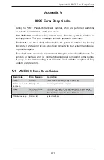
During the POST (Power-On Self-Test) routines, which are performed each time 

the system is powered on, errors may occur.

Non-fatal errors

 are those which, in most cases, allow the system to continue the 

boot-up process. The error messages normally appear on the screen.

Fatal errors

 are those which will not allow the system to continue the boot-up 

procedure. If a fatal error occurs, you should consult with your system manufacturer 

for possible repairs.

These fatal errors are usually communicated through a series of audible beeps. The 

numbers on the fatal error list (on the following page) correspond to the number 

of beeps for the corresponding error. All errors listed, with the exception of Beep 

Code 8, are fatal errors.

A-1  AMIBIOS Error Beep Codes

Beep Code

Error Message

Description

1 beep

Refresh

Circuits have been reset (Ready to power up)

5 short beeps and 1 
long beep

Memory error

No memory detected in the system

5 beeps

No Con-In or Con-
out devices

Con-In includes USB or PS/2 keyboard, PCi or Serial console 
redirection, IPMI KVM or SOL. Con-Out includes video controller, 
PCI or Serial console redirection or IPMI SOL.

1 Continuous beep

System OH

System Overheat

Summary of Contents for 2027TR-H70FRF

Page 1: ...SUPERSERVER 2027TR H70QRF 2027TR H70FRF 2027TR H70RF SUPER USER S MANUAL Revision 1 0 ...

Page 2: ...f any such disputes Super Micro s total liability for all claims will not exceed the price paid for the hardware product FCC Statement This equipment has been tested and found to comply with the limits for a Class A digital device pursuant to Part 15 of the FCC Rules These limits are designed to provide reasonable protection against harmful interference when the equipment is operated in a commerci...

Page 3: ...F H70QRF Model Variations Server Model X9DRT Serverboard InfiniBand QDR InfiniBand FDR 2027TR H70QRF X9DRT HIBQF YES 2027TR H70FRF X9DRT HIBFF YES 2027TR H70RF X9DRT HF Manual Organization Chapter 1 Introduction The first chapter provides a checklist of the main components included with the server system and describes the main features of the X9DRT HIBQF HIBFF HF serverboard and the SC217HQ R1620B...

Page 4: ...onnections headers and jumpers Refer to this chapter when adding or removing processors or main memory and when reconfiguring the serverboard Chapter 6 Advanced Chassis Setup Refer to Chapter 6 for detailed information on the SC217HQ R1620B server chassis You should follow the procedures given in this chapter when installing removing or reconfiguring SAS SATA or peripheral drives and when replacin...

Page 5: ...v SUPERSERVER 2027TR H70RF H70FRF H70QRF USER S MANUAL Notes ...

Page 6: ...1 4 I O Ports 1 4 Cooling System 1 4 Air Shrouds 1 4 Mounting Rails 1 5 1 4 Advanced Power Management 1 5 Intel Intelligent Power Node Manager IPNM 1 5 Manageability Engine ME 1 5 1 4 Contacting Supermicro 1 7 1 5 2U Twin2 System Notes 1 8 Nodes 1 8 System Power 1 8 SAS SATA Backplane Drives 1 8 Chapter 2 Server Installation 2 1 Overview 2 1 2 2 Unpacking the System 2 1 2 3 Preparing for Setup 2 1...

Page 7: ...rverboard Setup 2 9 2 7 Checking the Drive Bay Setup 2 11 Chapter 3 System Interface 3 1 Overview 3 1 3 2 Control Panel Button 3 2 3 3 Control Panel LEDs 3 2 3 4 Drive Carrier LEDs 3 3 Chapter 4 System Safety 4 1 Electrical Safety Precautions 4 1 4 2 General Safety Precautions 4 2 4 3 ESD Precautions 4 3 4 4 Operating Precautions 4 4 Chapter 5 Advanced Motherboard Setup 5 1 Handling the Motherboar...

Page 8: ... Sensitive Devices 6 1 Precautions 6 1 Unpacking 6 1 6 2 Control Panel 6 2 6 3 Chassis Cover 6 3 6 4 Air Shrouds 6 4 6 5 Checking the Airflow 6 5 6 6 System Fans 6 5 Optional Fan Configurations 6 5 6 7 Removing and Installing the Backplane 6 8 Removing the Backplane 6 8 Installing the Backplane 6 10 6 8 Installing the Motherboard 6 11 I O Shield 6 11 Permanent and Optional Standoffs 6 11 6 9 Adapt...

Page 9: ...w To Change the Configuration Data 7 1 Starting the Setup Utility 7 2 7 2 Advanced Settings Menu 7 2 7 3 Event Logs 7 20 4 4 IPMI 7 22 4 5 Boot 7 24 4 6 Security 7 25 4 7 Save Exit 7 25 Appendix A BIOS Error Beep Codes Appendix B System Specifications ix Table of Contents ...

Page 10: ...x Notes SUPERSERVER 2027TR H70RF H70FRF H70QRF USER S MANUAL ...

Page 11: ...nts have been included with the 2027TR H70RF H70FRF H70QRF server as listed below Four 4 Plastic air shrouds for SC827H HQ 217HQ chassis MCP 310 82715 0B Heat Sinks Four 4 1U passive CPU heat sinks for rear CPU SNK P0047PW Four 4 1U passive CPU heat sinks w narrow ILM SNK P0047PS Four 4 80x80x38mm cooling fans FAN 0129L4 SATA SAS Backplane Four 4 SAS2 backplanes BPN ADP SAS2 L6I O P One 1 24pcs 2 ...

Page 12: ...R3 1600 1333 1066 800 MHz speed registered ECC SDRAM in up to 512 MB 1 GB 2 GB 4 GB 8 GB 16 GB or 32 GB sizes at 1 35V or 1 5V voltages See Chapter 5 for details Note Check the Supermicro website www supermicro com for the latest memory support information SAS An LSI SAS2008 SAS2 controller is integrated into the BPN ADP SAS2 L6I O P backplane to provide an eight port 6 Gb s SAS2 Serial Attached S...

Page 13: ...server includes a QDR quad data rate speed InfiniBand QSFP connector The 2027TR H70FRF server includes a FDR fourteen data rate speed InfiniBand QSFP connector InfiniBand is a scalable serial communications link intended for connecting processors with high speed peripherals Other Features Other onboard features that promote system health include onboard voltage monitors a chassis intrusion header ...

Page 14: ...d control for one server node LEDs indicate system power HDD activity network activity system overheat and power supply failure A main power button and a system reset button are also included I O Ports The SC217 chassis designed to be used in a 2U rackmount configuration The SC217 chassis provides a low profile add on card slot a COM port a VGA port two USB 2 0 ports and two gigabit Ethernet ports...

Page 15: ...hough IPNM Specification Version 2 0 is supported by the BMC Baseboard Management Controller your system must also have IPNM compatible Manageability Engine ME 2 0 firmware installed to use this feature Manageability Engine ME The Manageability Engine which is an ARC controller embedded in the IOH I O Hub provides Server Platform Services SPS to your system The services provided by SPS are differe...

Page 16: ...E2 PE1 DMI Gen3 x16 x4 VGA BMC SH7757 DDR3 PHY1 LAN RTL8211 SPI SAS x1 U6H1 U7C1 U3G1 UM1 Gen2 Gen1 2 PCI E x16 SLOT x4 RJ45 RJ45 UL1 Gen3 x16 Gen3 x8 PCI E x8 in x4 SLOT Gen3 x8 PCI E x8 in x4 SLOT PCI E x16 customized SLOT Gen3 x16 x16 x8 8 15 QSFP x8 0 7 IB HOTSWAP INTERFACE SATA2 1 SATA2 2 SATA2 3 SATA2 4 SATA3 5 SATA3 6 SAS SATA3 1 SAS SATA3 2 SAS SATA3 3 SAS SATA3 4 SAS SATA3 5 SAS SATA3 6 S...

Page 17: ...ss Super Micro Computer B V Het Sterrenbeeld 28 5215 ML s Hertogenbosch The Netherlands Tel 31 0 73 6400390 Fax 31 0 73 6416525 Email sales supermicro nl General Information support supermicro nl Technical Support rma supermicro nl Customer Support Asia Pacific Address Super Micro Computer Inc 4F No 232 1 Liancheng Rd Chung Ho Dist New Taipei City 235 Taiwan R O C Tel 886 2 8226 3990 Fax 886 2 822...

Page 18: ...p when a node is fully installed If too much force is used when inserting a node this pin may break off Take care to slowly slide a node in until you hear the click of the locking tab seating itself System Power Dual 1620 Watt power supply is used to provide the power for all four serverboards Each serverboard however can be shut down independently of the other with the power button on its own con...

Page 19: ...aged in any way If the server itself shows damage you should file a damage claim with the carrier who delivered it Decide on a suitable location for the rack unit that will hold the 2027TR H70RF H70FRF H70QRF server It should be situated in a clean dust free area that is well ventilated Avoid areas where heat electrical noise and electromagnetic fields are generated You will also need it placed ne...

Page 20: ...rack installation stabilizers should be attached to the rack In multiple rack installations the racks should be coupled together Always make sure the rack is stable before extending a component from the rack You should extend only one component at a time extending two or more simultaneously may cause the rack to become unstable Server Precautions Review the electrical and general safety precaution...

Page 21: ...romised Mechanical Loading Equipment should be mounted into a rack so that a hazardous condition does not arise due to uneven mechanical loading Circuit Overloading Consideration should be given to the connection of the equipment to the power supply circuitry and the effect that any possible overloading of circuits might have on overcurrent protection and power supply wiring Appropriate considerat...

Page 22: ...his rail will fit a rack between 26 5 and 36 4 deep Identifying the Sections of the Rack Rails The chassis package includes two rail assemblies in the rack mounting kit Each assembly consists of three sections An inner chassis rail which secures directly to the chassis an outer rail that secures to the rack and a middle rail which extends from the outer rail see Figure 2 1 These assemblies are spe...

Page 23: ...out of the rack when when the chassis is pulled out for servicing Releasing the Inner Rail Use the procedure below to release the inner rails from the outer rails Releasing Inner Rail from the Outer Rails Figure 2 2 1 Identify the left and right outer rail assemblies as described in section 2 5 2 Pull the inner rail out of the outer rail until it is fully extended as illustrated below 3 Press the ...

Page 24: ...mly against the side of the chassis aligning the hooks on the side of the chassis with the holes in the inner rail 3 Slide the inner rail forward toward the front of the chassis until the rail clicks into the locked position which secures the inner rail to the chassis 4 Secure the inner rail to the chassis with the screws provided 5 Repeat steps 1 through 4 above for the other inner rail Figure 2 ...

Page 25: ... rail back into the outer rail 3 Hang the hooks of the front of the outer rail onto the slots on the front of the rack If necessary use screws to secure the outer rails to the rack as illustrated above 4 Pull out the rear of the outer rail adjusting the length until it fits within the posts of the rack 5 Hang the hooks of the rear portion of the outer rail onto the slots on the rear of the rack If...

Page 26: ...ition of the middle rail 4 Align the chassis inner rails with the front of the middle rails 5 Slide the inner rails on the chassis into the middle rails keeping the pressure even on both sides until the locking tab of the inner rail clicks into the front of the middle rail locking the chassis into the fully extended position 6 Depress the locking tabs of both sides at the same time and push the ch...

Page 27: ... the AC power cord from any external power source 2 Remove the two screws which secure the top cover onto the chassis as shown above 3 Lift the top cover up and off the chassis 4 Peel off the protective film covering the top cover and the top of the chassis 5 Check that all ventilation openings on the top cover and the top of the chassis are clear and unobstructed 6 Replace the chassis cover and r...

Page 28: ...F H70QRF server system may have come with system memory already installed Make sure all DIMMs are fully seated in their slots For details on adding system memory refer to Chapter 5 3 If desired you can install add on cards to the system See Chapter 5 for details on installing PCI add on cards 4 Make sure all power and data cables are properly connected and not blocking the chassis airflow Also mak...

Page 29: ... of the chassis In addition if you are using a front bezel make sure the bezel s filter is replaced periodically 2 Except for brief periods while swapping hard drives do not operate the server without drives or the drive carriers in the drive bays Use only recommended server parts 3 Make sure no wires or foreign objects obstruct airflow through the chassis Pull all excess cabling out of the airflo...

Page 30: ...2 12 SUPERSERVER 2027TR H70RF H70FRF H70QRF USER S MANUAL Notes ...

Page 31: ... the drive carriers to keep you constantly informed of the overall status of the system SC217 models include four front panels on the handles of the chassis which control each of the systems This chapter explains the meanings of all LED indicators and the appropriate response you may need to take Figure 3 1 Control Panel ...

Page 32: ... you must unplug the AC power cord from any external power source before servicing The power button has a built in LED which will turn green when the power is on UID When used with a UID compatible motherboard the UID button is used to turn on or off the blue light function of the LED This is built into the front side of the UID button and at the rear end of each motherboard node for those motherb...

Page 33: ... NIC Indicates network activity on either LAN1 or LAN2 when flashing 3 4 Drive Carrier LEDs The SC217 chassis uses SAS SATA drives SAS SATA Drives Each SAS SATA drive carrier has two LEDs Blue Each Serial ATA drive carrier has a blue LED When illuminated this blue LED on the front of the SAS SATA drive carrier indicates drive activity A connection to the SAS SATA backplane enables this LED to blin...

Page 34: ...SUPERSERVER 2027TR H70RF H70FRF H70QRF USER S MANUAL 3 4 Notes ...

Page 35: ...rds The unit has more than one power supply cord Disconnect two power supply cords before servicing to avoid electrical shock When working around exposed electrical circuits another person who is familiar with the power off controls should be nearby to switch off the power if necessary Use only one hand when working with powered on electrical equipment This is to avoid making a complete circuit wh...

Page 36: ...d free of clutter The 2027TR H70RF H70FRF H70QRF server weighs approximately 85 lbs 38 6kg when fully loaded When lifting the system two people at either end should lift slowly with their feet spread out to distribute the weight Always keep your back straight and lift with your legs Place the chassis top cover and any system components that have been removed away from the system or on a table so t...

Page 37: ...all components and printed circuit boards PCBs in their antistatic bags until ready for use Touch a grounded metal object before removing the board from the antistatic bag Do not let components or PCBs come into contact with your clothing which may retain a charge even if you are wearing a wrist strap Handle a board by its edges only do not touch its components peripheral chips memory modules or c...

Page 38: ...r if this practice is not strictly followed Figure 4 1 Installing the Onboard CR2032 Battery LITHIUM BATTERY BATTERY HOLDER Please handle used batteries carefully Do not damage the battery in any way a damaged battery may release hazardous materials into the environment Do not discard a used battery in the garbage or a public landfill Please comply with the regulations set up by your local hazardo...

Page 39: ... bending keep one hand under the center of the board to support it when handling The following measures are generally sufficient to protect your equipment from electric static discharge Precautions Use a grounded wrist strap designed to prevent Electrostatic Discharge ESD Touch a grounded metal object before removing any board from its antistatic bag Handle a board by its edges only do not touch i...

Page 40: ...peripheral devices have been carefully routed in preconfigured systems to prevent them from blocking the flow of cooling air that moves through the system from front to back If you need to disconnect any of these cables you should take care to reroute them as they were originally after reconnecting them make sure the red wires connect to the pin 1 locations If you are configuring the system keep t...

Page 41: ... below for the colors and locations of the various I O ports Figure 5 1 Rear I O Ports Back Panel I O Port Locations and Definitions 1 Back Panel USB Port 0 2 Back Panel USB Port 1 3 IPMI_Dedicated LAN 4 Gigabit LAN 1 5 Gigabit LAN 2 6 COM Port 1 Turquoise 7 Back Panel VGA Blue 8 InfiniBand Connector For X9DRT HIBQF HIBFF 9 UID Switch 2 1 5 3 4 6 7 9 8 ...

Page 42: ...s connect the power cord last and always remove it before adding removing or changing any hardware components Make sure that you install the processor into the CPU socket before you install the CPU heatsink Caution If you buy a CPU separately make sure that you use an Intel certified multi directional heatsink only Make sure to install the system board into the chassis before you install the CPU h...

Page 43: ...ARNING Press down on Load the Lever labeled Close 1st Pull lever away from the socket 3 With the lever labeled Close 1st fully retracted gently push down on the Open 1st lever to open the load plate Lift the load plate to open it completely Gently push down to pop the load plate open OPEN1st OPEN1st WARNING WARNING WARNING WARNING 4 Using your thumb and the index finger remove the WARNING plastic ...

Page 44: ...rop the CPU on the socket Do not move the CPU horizontally or vertically Do not rub the CPU against the surface or against any pins of the socket to avoid damaging the CPU or the socket Caution You can only install the CPU inside the socket in one direction Make sure that it is properly inserted into the CPU socket before closing the load plate If it doesn t close properly do not force it as it ma...

Page 45: ...ate with the CPU inside the socket Lock the lever labeled Close 1st first then lock the lever labeled Open 1st second Use your thumb to gently push the load levers down to the lever locks OPEN1st OPEN1st Push down and lock the level labeled Close 1st Gently close the load plate OPEN1st OPEN1st OPEN1st OPEN1st Lever Lock Lever Lock Push down and lock the lever labeled Open 1st ...

Page 46: ...les are aligned with those on the Motherboard s and the Heatsink Bracket underneath Make sure the heatsink is placed so that the fins of the heatsink are in the direction of the airflow in your system 3 Screw in two diagonal screws i e the 1 and the 2 screws until just snug do not over tighten the screws to avoid possible damage to the CPU 4 Finish the installation by fully tightening all four scr...

Page 47: ...ews from the motherboard in the sequence as shown in the illustration below 2 Gently wriggle the heatsink to loosen it from the CPU Do not use excessive force when wriggling the heatsink 3 Once the CPU is loosened remove the CPU from the CPU socket 4 Remove the used thermal grease and clean the surface of the CPU and the heatsink Reapply the proper amount of thermal grease on the surface before re...

Page 48: ...or 32 GB size size memory modules are supported It is highly recommended that you remove the power cord from the system before installing or changing memory modules Please refer to our web site for memory that has been tested on the X9DRT HIBQF HIBFF HF serverboard Memory Support The X9DRT HIBQF HIBFF HF serverboard supports single and dual channel DDR3 1600 1333 1066 800 MHz speed registered ECC ...

Page 49: ...2 CPUs 4 DIMMs CPU1 CPU2 P1 DIMMA1 P1 DIMMB1 P2 DIMME1 P2 DIMMF1 2 CPUs 6 DIMMs CPU1 CPU2 P1 DIMMA1 P1 DIMMB1 P2 DIMME1 P2 DIMMF1 P1 DIMMC1 P1 DIMMD1 2 CPUs 8 DIMMs CPU1 CPU P1 DIMMA1 P1 DIMMB1 P2 DIMME1 P2 DIMMF1 P1 DIMMC1 P1 DIMMD1 P2 DIMMG1 P2 DIMMH1 To Install Insert module vertically and press down until it snaps into place Pay attention to the alignment notch at the bottom To Remove Use your...

Page 50: ...ed per DDR Channel LRDIMM Type Load Reduced DIMM POR Speeds in MHz Ranks per DIMM Any Combination 1 LR ECC DDR3 1066 1333 QR Note 1 For the memory modules to work properly please install DIMM modules in pairs w even number of DIMMs installed Note 2 All channels in a system will run at the fastest common frequency Possible System Memory Allocation Availability System Device Size Physical Memory Ava...

Page 51: ...e PCI Express x16 cards to fit inside the chassis Installing an Expansion Card 1 After powering down the system remove the PCI slot shield 2 Fully seat the card into the slot pushing down with your thumbs evenly on both sides of the card 3 Finish by using a screw to secure the top of the card shield to the chassis The PCI slot shield protects the motherboard and its components from EMI and aid in ...

Page 52: ...JWP1 JBR1 JRK1 JF2 JBT1 LEB1 LEB2 LEM1 LE3 JB1 JI2C2 JI2C1 JNMI1 JRST1 JIB1 LE2 JTPM1 BATTERY InfiniBand Controller C602 Chipset InfiniBand FDR QDR S SATA0 I SATA1 I SATA0 S SATA3 S SATA2 SXB4 PCI E 3 0 X16 LE1 SXB3 PCI E 3 0 X8 P2 DIMMG1 P2 DIMMH1 P2 DIMME1 P1 DIMMB1 P1 DIMMA1 RAID KEY COM1 VGA CPU1 SXB1 PCI E 3 0 X16 SXB2 PCI E 3 0 X8 LAN1 USB0 1 IPMI_LAN LAN2 USB2 CPU2 P1 DIMMC1 SW1 UID P1 DIMM...

Page 53: ...as the graphics shown in this manual X9DRT HIBQF HIBFF HF Quick Reference Jumper Description Default Setting JBT1 Clear CMOS See Chapter 3 JIB1I InfiniBand Enable X9DRT HIBQF X9DRT HIBFF only Pins 1 2 Enabled JI2C1 JI2C2 SMB to PCI E Slots Pins 2 3 Normal JPB1 BMC Enabled Pins 1 2 Enabled JPG1 VGA Enabled Pins 1 2 Enabled JPL1 Ethernet GLAN1 GLAN2 Enable Pins 1 2 Enabled JWD Watch Dog Pins 1 2 Res...

Page 54: ...s JNMI1 NMI Non Maskable Interrupt Header JIPMB1 4 pin External BMC I2 C Header for an IPMI Card JRST1 Alarm Reset Header JPTM1 TPM Trusted Platform Module Port 80 JSD1 SATA DOM Device_On_Module Power Connector LAN1 2 G bit Ethernet Ports 1 2 IPMI LAN IPMI_Dedicated LAN Slot1 PCI E 3 0 x16 Slot SXB1 PCI E 3 0 x8 Slot for Rear I O Riser Card SXB2 PCI E 3 0 x8 Slot for SMC Proprietary Daughter Add O...

Page 55: ...ct LED 3 TD0 12 P3V3SB 4 TD1 13 Link 100 LED Yellow 3V3SB 5 TD1 14 Link 1000 LED Yellow 3V3SB 6 TD2 15 Ground 7 TD2 16 Ground 8 TD3 17 Ground 9 TD3 18 Ground NC indicates no connection Universal Serial Bus USB Two Universal Serial Bus ports USB 0 1 are located on the I O back panel In addition a USB header located next to I SATA 5 provides two front accessible USB connections USB 2 3 Cables are no...

Page 56: ...Connection Both the X9DRT HIBQF and X9DRT HIBFF serverboards have an onboard InfiniBand IB connector which is located on the rear IO panel on the motherboard The IB switch is primarily used for High performance computing See the table on the right for pin definitions InfiniBand IB Pin Definitions Pin Definition Pin Definition S1 Input Pair0 Pos S9 Output Pair3 Pos S2 Input Pair0 Neg S10 Output Pai...

Page 57: ...d of service See the table on the right for pin definitions Note UID LED is supported by the physical switch or the BMC When it is controlled by the physical switch it will stay solid When it is controlled by the BMC it will blink UID Switch Pin Definition 1 Ground 2 Ground 3 Button In 4 Ground UID Switches LEDs Description Location FP Switch Pin 16 on JF2 Rear Switch SW1 FP UID LED Blue LED Pin 1...

Page 58: ...ovide TPM support and Port 80 connection Use this header to enhance system performance and data security See the table on the right for pin definitions TPM Port 80 Header JTPM1 Pin Definitions Pin Definition Pin Definition 1 LCLK 2 GND 3 LFRAME 4 KEY 5 LRESET 6 5V X 7 LAD 3 8 LAD 2 9 3 3V 10 LAD1 11 LAD0 12 GND 13 SMB_CLK4 14 SMB_DAT4 15 3V_DUAL 16 SERIRQ 17 GND 18 CLKRUN X 19 LPCPD 20 LDRQ X JTAG...

Page 59: ... Enable Disable JPL1 enables or disables the GLAN 1 2 ports on the motherboard See the table on the right for jumper settings The default setting is Enabled GLAN Enable Jumper Settings Jumper Setting Definition 1 2 Enabled default 2 3 Disabled CMOS Clear JBT1 is used to clear CMOS which will also clear any passwords Instead of pins this jumper consists of contact pads to prevent accidentally clear...

Page 60: ...is 1 2 to enable the connection See the table on the right for jumper settings VGA Enable JPG1 Jumper Settings Jumper Setting Definition 1 2 Enabled Default 2 3 Disabled BMC Enable Jumper JPB1 allows you to enable the onboard BMC Baseboard Management Controller to provide IPMI 2 O KVM support on the motherboard See the table on the right for jumper settings BMC Enable JPB1 Jumper Settings Jumper S...

Page 61: ...The Gigabit LAN ports are located on the IO Backplane on the motherboard On each Gb LAN port one LED blinks to indicate activity while the other may be green amber or off to indicate the speed of the connection See the table on the right for the functions associated with the connection speed LED Onboard Power LED An Onboard Power LED is located at LE1 on the motherboard When this LED is on the sys...

Page 62: ...ied Blue Blinking Linux OS Unit Identified InfiniBand Link LED LEB1 Settings Color Status Definition Green Solid InfiniBand Connected Off Off No connection InfiniBand Activity LED LEB2 Settings Color Status Definition Yellow Solid InfiniBand Active Yellow Dim InfiniBand Connected Activity Idle Off Off No connection InfiniBand LED Indicators B o t h t h e X 9 D R T H I B Q F a n d X9DRT HIBFF serve...

Page 63: ...r a rear IO riser card while Slot SXB2 supports the SMC proprietary daughter card Refer to the layout below for the locations Serial ATA SATA Connections A Front Panel Add On Card header is located at JF2 on the motherboard This header provides onboard SATA support Plug an add on card in JF2 to use SATA connections In addition two SATA connections I SATA 0 1 located next to the Intel PCH chip also...

Page 64: ...pear If this display does not appear click on the My Computer icon and then on the icon representing your CD ROM drive Finally double click on the S Setup icon Click the icons showing a hand writing on paper to view the readme files for each item Click the computer icons to the right of these items to install each item from top to the bottom one at a time After installing each item you should rebo...

Page 65: ...al system information such as CPU temperature system voltages and fan status See the Figure below for a display of the SuperDoctor III interface Note The default User Name and Password for SuperDoctor III is ADMIN ADMIN Note When SuperDoctor is first installed it adopts the temperature threshold settings that have been set in BIOS Any subsequent changes to these thresholds must be made within Supe...

Page 66: ...ram and User s Manual can be downloaded from the Supermicro web site at http www supermicro com products accessories software SuperDoctorIII cfm For Linux we recommend that you use the SuperoDoctor II application instead Figure 5 6 Supero Doctor III Interface Display Screen Remote Control ...

Page 67: ...turer CR2032 Dispose of used batteries according to the manufacturer s instructions Figure 5 7 Installing the Onboard Battery LITHIUM BATTERY BATTERY HOLDER Please handle used batteries carefully Do not damage the battery in any way a damaged battery may release hazardous materials into the environment Do not discard a used battery in the garbage or a public landfill Please comply with the regulat...

Page 68: ...5 30 SUPERSERVER 2027TR H70RF H70FRF H70QRF USER S MANUAL Notes ...

Page 69: ...very carefully The following measures are generally sufficient to protect your equipment from ESD damage Precautions Use a grounded wrist strap designed to prevent static discharge Touch a grounded metal object before removing any board from its antistatic bag Handle a board by its edges only do not touch its components peripheral chips memory modules or gold contacts When handling chips or module...

Page 70: ...s The LEDs inform you of system status See Chapter 3 for details on the LEDs and the control panel buttons Figure 6 1 Front and Rear Chassis Views SATA SAS Drives 24 Control Panel Control Panel Control Panel Control Panel Ethernet Ports USB Ports VGA Port IPMI LAN Port COM1 Port Infiniband Port 2027TR H70QRF and 2027TR H70FRF only ...

Page 71: ...er onto the chassis as shown above 3 Lift the top cover up and off the chassis 4 Peel off the protective film covering the top cover and the top of the chassis 5 Check that all ventilation openings on the top cover and the top of the chassis are clear and unobstructed 6 Replace the chassis cover and reconnect the AC power cord Figure 6 2 Removing the Chassis Cover Caution Except for short periods ...

Page 72: ...ustrations below Installing an Air Shroud Figure 6 3 1 Make sure that the motherboard expansion card if applicable and all components are properly installed in each motherboard node 2 Place the first air shroud over the motherboard as shown below The air shroud sits behind the system fans and goes over the top of the motherboard and its components 3 Repeat the procedure for the remaining three mot...

Page 73: ...cooling for the chassis These fans circulate air through the chassis as a means of lowering the chassis internal temperature The SC217 system fans are easy to change modules There is no need to uninstall any other parts inside the system when replacing fans and no tools are required for installation Optional Fan Configurations The SC217H model chassis is designed so that the default configuration ...

Page 74: ... fan housing up and out of the chassis 4 Push the fan up from the bottom and out of the top of the housing 5 Place the replacement fan into the vacant space in the housing while making sure the arrows on the top of the fan indicating air direction point in the same direction as the arrows on the other fans 6 Put the fan back into the chassis and reconnect the cable see Figure 6 4 and Figure 6 5 fo...

Page 75: ...Chapter 6 Advanced Chassis Setup 6 7 Figure 6 5 Replacing a System Fan in the Fan Housing ...

Page 76: ... instructions below Removing the Backplane Removing the Backplane from the Chassis 1 Power down and unplug the system from any power source 2 Remove the chassis cover 3 Disconnect the cabling to the backplane 4 Remove all of the hard drive carriers from the front of the chassis 5 Remove the five upper screws at the top of the backplane and the screw from the side of the chassis as indicated by the...

Page 77: ...ated on the floor of the chassis indicated by the arrows below Figure 6 7 7 Gently ease the backplane up and out of the chassis at a slight angle Figure 6 8 Figure 6 7 Loosening the Spring Bar Screws in the Floor of the Chassis Figure 6 8 Removing the Backplane from the Chassis 1 6 1 7 ...

Page 78: ...ed 3 Slide the backplane into the chassis at a slight angle pushing it up against the side of the chassis 4 Ease the backplane forward against the front of the chassis This will aid in the alignment of the mounting holes 5 Align the mounting holes in the backplane with the holes in the chassis Replace the four screws at the top of the backplane and the screw on the side of the chassis 6 Adjust the...

Page 79: ...ws for heatsinks general components and or non standard security Optional standoffs are used for these motherboards To use an optional standoff you must place a hexagonal screw through the bottom the chassis and secure the screw with the hexagonal nut rounded side up Depending upon the configuration of the motherboard being used it is also possible that some of the optional standoffs which are pre...

Page 80: ...ated with the motherboard if the chassis is a hot swappable version Refer to the next section for instructions on installing the adapter card 8 Secure the CPU s heatsinks and other components to the motherboard as described in the motherboard documentation 9 Connect the cables between the motherboard backplane chassis front panel and power supply as needed Also fans may be temporarily removed to a...

Page 81: ...Chapter 6 Advanced Chassis Setup 6 13 Figure 6 12 Installing the Motherboard in the Motherboard Node Drawer ...

Page 82: ...spacer plate to the drawer and set them aside for later use 5 Remove the adapter card and spacer plate from the motherboard drawer 6 Set the spacer plate aside for later use Installing the Adapter Card Figure 6 13 1 Make sure the motherboard has been installed properly in the node drawer before installing the adapter card 2 Place the adapter card and spacer plate in the motherboard drawer aligning...

Page 83: ...chassis on a flat surface 2 Pull the motherboard node drawer from the chassis 3 Remove the expansion card bracket 3a Remove the screw securing the expansion bracket to the back of the drawer 3b Lift the bracket out of the motherboard node drawer 4 Align the riser card mounting hole to the bracket standoff and secure the riser card to the bracket using the two screws included in the accessory box 5...

Page 84: ...n the rear of the motherboard node drawer 4 Remove the PCI PCI slot shield 5 Place the expansion card into the motherboard node drawer 6 Slide the expansion card into the rear riser card PCI slot and fit the expansion card bracket with the opening in the rear of the motherboard node drawer 7 Close the expansion card PCI slot clip 8 Close the cover reconnect the power supply and power up the chassi...

Page 85: ...additional inmformation http www supermicro com support manuals The SC217 chassis contains four individual motherboards in separate node drawers Each motherboard node controls a set of six hard drives Note that if a motherboard node drawer is pulled out of the chassis the hard drives associated with that node will power down as well Motherboard Drawer Locations in the Chassis Motherboard B Control...

Page 86: ...igure 6 17 1 Press the release button on the drive tray This extends the drive bay handle 2 Use the handle to pull the drive out of the chassis Figure 6 17 Removing Hard Drive 1 1 1 2 Cauton Except for short periods of time while swapping hard drives do not operate the server with the hard drives empty ...

Page 87: ...r 3 Install a new drive into the carrier with the printed circuit board side facing down so that the mounting holes align with those in the carrier 4 Secure the hard drive by tightening all four 4 screws 5 Use the open handle to replace the drive carrier into the chassis Make sure to close the drive carrier handle Dummy Drive Hard Drive Carrier Caution Enterprise level hard disk drives are recomme...

Page 88: ...pply Replacement The SC217 chassis utilizes two redundant power supplies In the unlikely event that the power supply unit needs to be replaced one power supply can be removed without powering down the system Replacement units can be ordered directly from Supermicro See the contact information in the Preface of this manual Changing the Power Supply 1 Push the release tab on the back of the power su...

Page 89: ... options cannot be configured Options in blue can be configured by the user The right frame displays the key legend Above the key legend is an area reserved for a text message When an option is selected in the left frame it is highlighted in white Often a text message will accompany it Note the AMI BIOS has default text messages built in Supermicro retains the option to include omit or change any ...

Page 90: ... to update the BIOS do not shut down or reset the system while the BIOS is updating This is to avoid possible boot failure 7 2 Advanced Settings Menu Boot Feature Quiet Boot This feature selects the bootup screen display between POST messages and the OEM logo Select Disabled to display the POST messages Select Enabled to display the OEM logo instead of the normal POST messages The options are Enab...

Page 91: ...w the system to reboot when it is inactive for more than 5 minutes The options are Enabled and Disabled Power Button Function If this feature is set to Instant_Off the system will power off immediately as soon as the user presses the power button If this feature is set to 4_Second_Override the system will power off when the user presses the power button for 4 seconds or longer The options are Inst...

Page 92: ...ntel HT Hyper Threading Technology Intel VT x Technology Intel SMX Technology L1 Data Cache L1 Code Cache L2 Cache L3 Cache CPU Speed This item displays the speed of the CPU installed in Cpu Socket 1 or Socket 2 64 bit This item indicates if the CPU installed in Socket 1 or 2 supports 64 bit technology Clock Spread Spectrum Select Enable to enable Clock Spectrum support which will allow the BIOS t...

Page 93: ...vanced Encryption Standard AES New Instructions NI to ensure data security The options are Enabled and Disabled Hardware Prefetcher Available when supported by the CPU If set to Enabled the hardware prefetcher will prefetch streams of data and instructions from the main memory to the L2 cache to improve CPU performance The options are Disabled and Enabled Adjacent Cache Line Prefetch Available whe...

Page 94: ... saving mode Select Custom to customize system power settings Select Disabled to disable power saving settings The options are Disable Energy Efficiency and Custom Factory Long Duration Power Limit This item displays the power limit set by the manufacturer during which long duration power is maintained Long Duration Power Limit This item displays the power limit set by the manufacturer during whic...

Page 95: ...tural improvements freeing up the system resource for other tasks The options are Disabled and Enabled DCA Support Select Enabled to use Intel s DCA Direct Cache Access Technology to improve data transfer efficiency The options are Enabled and Disabled IIO 1 PCIe Port Bifuracation Control This submenu allows the user to configure the following IO PCIe Port Bifurcation Control settings for IIO 1 PC...

Page 96: ...le PCI Exp Generation 1 support for Port 3A Select GEN2 to enable PCI Exp Generation 2 support for Port 3A Select GEN3 to enable PCI Exp Generation 3 support for Port 3A The options are GEN1 GEN2 and GEN3 Port 3C Link Speed Select GEN1 to enable PCI Exp Generation 1 support for Port 3C Select GEN2 to enable PCI Exp Generation 2 support for Port 3C Select GEN3 to enable PCI Exp Generation 3 support...

Page 97: ...Configuration Current QPI Link Speed This item displays the speed of the QPI Link Isoc Select Enabled to enable Ischronous support to meet QoS Quality of Service requirements This feature is especially important for virtualization technology The options are Disabled and Enabled Current QPI Frequency This item displays the frequency of the QPI Link QPI Quick Path Interconnect Link Speed Mode Use th...

Page 98: ...ntical copies of all data in memory for data backup When Lockstep is selected the motherboard uses two areas of memory to run the same set of operations in parallel The options are Independent Mirroring Lockstep and Sparing DRAM RAPL Running Average Power Limit Mode This item sets the average power consumption limit on a DRAM module when it is in operation The options are Disabled DRAM RAPL Mode0 ...

Page 99: ...ng is a process that allows the CPU to correct correctable memory errors found on a memory module When the CPU or I O issues a demand read command and the read data from memory turns out to be a correctable error the error is corrected and sent to the requestor the original source Memory is updated as well Select Enabled to use Demand Scrubbing for ECC memory correction The options are Enabled and...

Page 100: ...ced Host Controller Interface EHCI Controller 1 Controller 2 The options are Disabled and Enabled Legacy USB Support Available when USB Functions is not Disabled Select Enabled to support legacy USB devices Select Auto to disable legacy support if USB devices are not present Select Disable to have USB devices available for EFI Extensive Firmware Interface applications only The settings are Disable...

Page 101: ...ty mode The options for Controller 0 are Enhanced and Compatible The default of SATA Controller 1 is Enhanced AHCI Mode The following items are displayed when the AHCI Mode is selected Aggressive Link Power Management Select Enabled to enable Aggressive Link Power Management support for Cougar Point B0 stepping and beyond The options are Enabled and Disabled Port 0 5 Hot Plug Select Enabled to ena...

Page 102: ...lly detect the presence of a SCU port and display the status of this port as detected PCIe PCI PnP Configuration PCI ROM Priority Use this feature to select the Option ROM to boot the system when there are multiple Option ROMs available in the system The options are EFI Compatible ROM and Legacy ROM PCI Latency Timer Use this feature to set the latency Timer of each PCI device installed on a PCI b...

Page 103: ...The options are Disabled Force L0 and Auto Warning Enabling ASPM support may cause some PCI E devices to fail SXB1 PCI E 3 0 x16 Option ROM Select Enabled to enable CPU1 SXB1 PCI E 3 0 x16 Option ROM to boot the system via a device installed on this slot The options are Disabled and Enabled SXB3 PCI E 3 0 x16 Option ROM Select Enabled to enable CPU2 SXB3 PCI E 3 0 x16 Option ROM to boot the system...

Page 104: ...ed and Disabled Device Settings This feature displays the serial port settings as specified Change Settings Use this feature to set the settings of a serial port specified The options are Auto IO 3F8h IRQ 4 IO 3F8h IRQ 3 IO 2F8h IRQ 3 IO 3E8h IRQ 5 IO 2E8h IRQ 7 IO 3F8h IRQ 3 4 5 6 7 10 11 12 IO 2F8h IRQ 3 4 5 6 7 10 11 12 IO 3E8h IRQ 3 4 5 6 7 10 11 12 and IO 2E8h IRQ 3 4 5 6 7 10 11 12 Device Mo...

Page 105: ...ces EMS The submenu allows the user to configure the following Console Redirection settings to support Out of Band Serial Port management Console Redirection Select Enabled to use a COM Port selected by the user for Console Redirection The options are Enabled and Disabled Console Redirection Settings This item determines how the host system exchanges data with the client computer Terminal Type Thi...

Page 106: ... sent along with the data bits Select Space to add a Space as a parity bit to be sent with your data bits The options are None Even Odd Mark and Space Stop Bits A stop bit indicates the end of a serial data packet Select 1 Stop Bit for standard serial data communication Select 2 Stop Bits if slower devices are used The options are 1 and 2 ACPI Setting Use this feature to configure Advanced Configu...

Page 107: ...Subsystem Configuration This feature displays the following ME Subsystem Configuration settings ME BIOS Interface Version ME Version iSCSI This item displays the following iSCSI information iSCSI Initiation Name This item displays the name of the iSCSI Initiator which is a unique name used in the world Intel 1350 Gigabit Network Connection This item displays the following iSCSI Internet Connection...

Page 108: ...er to configure SMBIOS Event settings Enabling Disabling Options SMBIOS Event Log Select Enabled to enable SMBIOS System Management BIOS Event Logging during system boot The options are Enabled and Disabled Runtime Error Logging Support Select Enabled to support Runtime Error Logging The options are Enabled and Disabled Memory Correctable Error Threshold This feature allows the user to enter the t...

Page 109: ...mmediately SMBIOS Event Log Standard Settings Log System Boot Event Select Enabled to log system boot events The options are Disabled and Enabled MECI Multiple Event Count Increment Enter the increment value for the multiple event counter Enter a number between 1 to 255 The default setting is 1 METW Multiple Event Count Time Window This item allows the user to decide how long in minutes should the...

Page 110: ...pon next system reboot Select Yes On every reset to erase all system event logs upon each system reboot Select No to keep all system event logs after each system reboot The options are No Yes On next reset and Yes On every reset When SEL is Full This feature allows the user to decide what the BIOS should do when the system event log is full Select Erase Immediately to erase all events in the log w...

Page 111: ...f DHCP is selected the BIOS will search for a DHCP Dynamic Host Configuration Protocol server in the network that is attached to and request the next available IP address for this computer The options are DHCP and Static The following items are assigned IP addresses automatically if DHCP is selected Station IP Address This item displays the Station IP address for this computer This should be in de...

Page 112: ...first boot drive Select a LAN device to boot the system from the network connection Select UEFI to boot the system from the UEFI Built in EFI Shell The options are LAN Device UEFI Built in EFI Shell and Disabled Boot Option 2 Use this item to select the first boot device Select a LAN device to boot the system from the network connection Select UEFI to boot the system from the UEFI Built in EFI She...

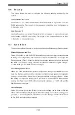
Page 113: ... computer Select Discard Changes and Exit and press Enter When the dialog box appears asking you if you want to exit the BIOS setup without saving click Yes to quit BIOS without saving the changes or click No to quit the BIOS and save changes Save Changes and Reset When you have completed the system configuration changes select this option to save the changes and reboot the computer so that the ne...

Page 114: ... Save as User Defaults Select this feature and press Enter to save the current settings as the user s defaults When the dialog box appears asking you if you want to save values as user s defaults click Yes to save the current values as user s default settings or click No to keep the defaults previously saved as the user s defaults Restore User Defaults Select this feature and press Enter to load t...

Page 115: ... These fatal errors are usually communicated through a series of audible beeps The numbers on the fatal error list on the following page correspond to the number of beeps for the corresponding error All errors listed with the exception of Beep Code 8 are fatal errors A 1 AMIBIOS Error Beep Codes Beep Code Error Message Description 1 beep Refresh Circuits have been reset Ready to power up 5 short b...

Page 116: ...A 2 SUPERSERVER 2027TR H70RF H70FRF H70QRF USER S MANUAL Notes ...

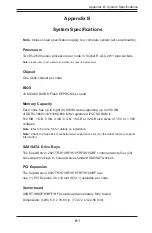
Page 117: ...R3 1600 1333 1066 800 MHz registered ECC SDRAM in 512 MB 1 GB 2 GB 4 GB 8 GB 16 GB or 32 GB size sizes of 1 5V or 1 35V voltages Note refer to Section 5 6 for details on installation Note Check the Supermicro website www supermicro com for the latest memory support information SAS SATA Drive Bays The SuperServer 2027TR H70RF H70FRF H70QRF contains twenty four 24 hot swap drive bays to house twelve...

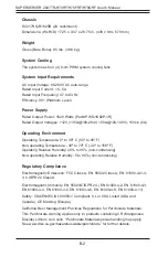
Page 118: ...to 95º F Non operating Temperature 40º to 70º C 40º to 158º F Operating Relative Humidity 20 to 95 non condensing Non operating Relative Humidity 5 to 95 non condensing Regulatory Compliance Electromagnetic Emissions FCC Class A EN 55022 Class A EN 61000 3 2 3 3 CISPR 22 Class A Electromagnetic Immunity EN 55024 CISPR 24 EN 61000 4 2 EN 61000 4 3 EN 61000 4 4 EN 61000 4 5 EN 61000 4 6 EN 61000 4 8...

Page 119: ...B 3 Appendix B System Specifications Notes ...

Page 120: ...ure to perform be reasonably expected to result in significant injury or loss of life or catastrophic property damage Accordingly Supermicro disclaims any and all liability and should buyer use or sell such products for use in such ultra hazardous applications it does so entirely at its own risk Furthermore buyer agrees to fully indemnify defend and hold Supermicro harmless for and against any and...

Reviews: