


42
SuperStorageSystem SSG-5019D8-TR12P User's Manual
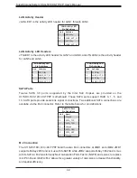
LAN Activity LED Headers
JTGLED1 is the activity LED header for LAN7 and LAN8, and JTGLED2 is the activity header
for LAN5 and LAN6.
LAN Activity LED
Pin Definitions
Pin#
Definition
1
3V3 Stby
2
LAN5_ACT_N
3
3V3 Stby
4
LAN6_ACT_N
LAN Activity LED
Pin Definitions
Pin#
Definition
1
3V3 Stby
2
LAN7_ACT_N
3
3V3 Stby
4
LAN8_ACT_N
LAN Activity Header
JLANLED1 is the activity LED header for LAN1 through LAN4.
LAN Activity LED
Pin Definitions
Pin#
Definition
1
3V3 Stby
2
LAN3_ACT_N
3
3V3 Stby
4
LAN4_ACT_N
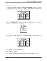
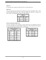
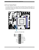
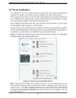
SATA Ports
Twelve SATA 3.0 ports, supported by the Intel SoC chipset, are provided on the
X11SDV-16C/-12C/-8C-TP8F motherboard. These SATA ports support RAID 0, 1, 5, and
10. SATA ports provide serial-link signal connections. Two additional SATA connections are
availabe via the M.2 connector. Refer to the table below for pin definitions.
SATA 3.0 Port
Pin Definitions
Pin#
Signal
1
Ground
2
SATA_TXP
3
SATA_TXN
4
Ground
5
SATA_RXN
6
SATA_RXP
7
Ground
M.2 Connection
The X11SDV-16C/-12C/-8C-TP8F board has two M.2 connectors at JMD1 and JMD2. JMD1
supports M-Key 2280 and is mux with S-SATA5 while JMD2 supports B-Key 3042 and is mux
with S-SATA4. M.2 was formerly Next Generation Form Factor (NGFF) and serves to replace
mini PCI-E and mSATA. M.2 allows for a greater variety of card sizes, increased functionality,
and spatial efficiency.