background image

5-22

S

UPER

S

ERVER 8045C-3R User's Manual

5-11 Onboard Indicators

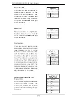
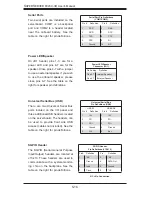
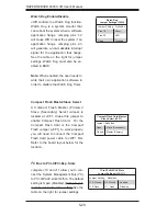
GLAN1/2 LEDs

The Ethernet ports (located beside 

the VGA port) have two LEDs. On 

each port, one LED indicates activity 

while the other LED may be green, 

amber or off to indicate the speed of 

the connection. See the table on the 

right for the functions associated with 

the connection speed LED.

GLAN1/2 LED 

(Connection Speed Indicator)

LED Color     Defi nition     

Off

10 MHz

Green

100 MHz

Amber

1 GHz

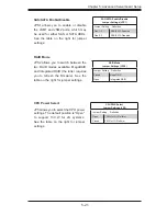
Onboard Power LED (LE1)

An Onboard Power LED is located at 

LE1. This LED Indicator is on when 

the system is on. Be sure to unplug 

the power cable before removing or 

adding any components. See the table 

on the right for more details.

Onboard PWR LED Indicator

(LE1)

LED Color     Defi nition     

Off

System Off (PWR cable 
not connected)

Green

System On

Green: 
Flashing 
Quickly

ACPI S1 State

Green: 
Flashing 
Slowly

ACPI S3 (STR) State

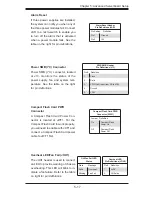
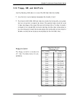
SAS Activity LED

LES1 is used to indicate the status of 

SAS activity.

SAS Activity LED  Indicator

(LES1)

LED Color     Defi nition     

On

SAS Port Active

Off

SAS Port Inactive

SAS Heartbeat LED

A SAS Heartbeat LED is located at 

LES2. When on, it indicates that the 

LSI1068E SAS controller is operat-

ing.

Summary of Contents for SUPERSERVER 8045C-3R

Page 1: ...SUPER SUPERSERVER 8045C 3R USER S MANUAL Revision 1 0 ...

Page 2: ... laws of Santa Clara County in the State of California USA The State of California County of Santa Clara shall be the exclusive venue for the resolution of any such disputes Super Micro s total liability for all claims will not exceed the price paid for the hardware product FCC Statement This equipment has been tested and found to comply with the limits for a Class A digital device pursuant to Par...

Page 3: ...the main features of the Super X7QC3 serverboard and the SC748TQ R1200 chassis Chapter 2 Server Installation This chapter describes the steps necessary to install the SuperServer 8045C 3R into a rack and check out the server configuration prior to powering up the system If your server was ordered without the processor and memory components this chapter will refer you to the appropriate sections of ...

Page 4: ...d Chassis Setup Refer to Chapter 6 for detailed information on the SC748TQ R1200 server chassis You should follow the procedures given in this chapter when installing removing or reconfiguring SAS or peripheral drives and when replacing system power supply units and cooling fans Chapter 7 BIOS The BIOS chapter includes an introduction to BIOS and provides detailed informa tion on running the CMOS S...

Page 5: ...v Preface Notes ...

Page 6: ...er 1 4 SATA Subsystem 1 4 Front Control Panel 1 4 I O Backplane 1 4 Cooling System 1 4 1 4 Contacting Supermicro 1 6 Chapter 2 Server Installation 2 1 Overview 2 1 2 2 Unpacking the System 2 1 2 3 Preparing for Setup 2 1 Rack Precautions Server Precautions Choosing a Setup Location 2 2 Rack Precautions 2 2 Server Precautions 2 2 Rack Mounting Considerations 2 3 Ambient Operating Temperature 2 3 Re...

Page 7: ...SAS Drive Carrier LEDs 3 3 Chapter 4 System Safety 4 1 Electrical Safety Precautions 4 1 4 2 General Safety Precautions 4 2 4 3 ESD Precautions 4 3 4 4 Operating Precautions 4 4 Chapter 5 Advanced Serverboard Setup 5 1 Handling the Serverboard 5 1 Precautions 5 1 Unpacking 5 2 5 2 Serverboard Installation 5 2 5 3 Connecting Cables 5 3 Connecting Data Cables 5 3 Connecting Power Cables 5 3 Connecti...

Page 8: ...ilure 6 4 Replacing Chassis Fans 6 4 6 4 Drive Bay Installation 6 6 SAS SATA Drives 6 6 SAS SATA Backplane 6 6 Installing Components in the 5 25 Drive Bays 6 8 6 5 Power Supply 6 9 Power Supply Failure 6 9 Removing Replacing the Power Supply 6 9 Chapter 7 BIOS 7 1 Introduction 7 1 Starting BIOS Setup Utility 7 1 7 2 Main Setup 7 2 7 3 Advanced Settings 7 3 7 5 Security Settings 7 23 7 6 Exit Optio...

Page 9: ... various hardware components have been included with the SuperServer 8045C 3R as listed below Four 4 CPU passive heat sinks SNK P0029P Two 2 CPU retention brackets BKT 0021L Three 3 8 cm rear chassis fans FAN 0081 Three 3 9 cm hot swap chassis fans FAN 0090 One 1 air shroud MCP 310 82801 0N One 1 floppy drive FPD PNSC 01 One 1 rail set MCP 290 00001 00 SAS Accessories One 1 SAS backplane CSE SAS M3...

Page 10: ...y are all supported Modules of the same size and speed should be used See Chapter 5 Section 5 for details Serial Attached SCSI SAS An onboard LSI 1068E Serial Attached SCSI SAS controller is integrated into the X7QC3 which supports eight SAS hard drives with SES2 The SAS drives are connected to a backplane that provides power bus termination and configuration settings and are hot swappable units No...

Page 11: ...on high reliability and superior longevity IPMI IPMI Intelligent Platform Management Interface is a hardware level interface speci fication that provides remote access monitoring and administration for Supermicro server platforms IPMI allows server administrators to view a server s hardware status remotely receive an alarm automatically if a failure occurs and power cycle a system that is non respo...

Page 12: ...g and control LEDs indicate system power HDD activity network activity system overheat and power supply failure A main power button and a system reset button are also included In addition two USB ports have been incorporated into the front of the chassis for convenient access I O Backplane The SC748TQ R1200 is a tower chassis that may be utilized in a 4U rackmount configuration The I O backplane in...

Page 13: ...SI 1068E ATI ES1000 32MB DDR2 SDRAM DB15VGA Port 480Mb S 480Mb S 480Mb S 480Mb S 480Mb S 480Mb S IDE S IDE M 17 GB s for 533MHz 21 GB s for 667MHz NorthBound IN x14 SouthBound OUTx10 4 25GB S 17GB S 4 CHs 1 CH READ WRITE 8 5GB S DDR2 533 5 3GB S 21GB S 4 CHs 1 CH READ WRITE 10 7GB S DDR2 667 LPC BUS BIOS 33MHz x4b SIO Winbond W 83627HF Serial Port FDD PS 2 KB MS Serial Port SOL BMC IPMI 2 0 PCI X ...

Page 14: ... Address Super Micro Computer B V Het Sterrenbeeld 28 5215 ML s Hertogenbosch The Netherlands Tel 31 0 73 6400390 Fax 31 0 73 6416525 Email sales supermicro nl General Information support supermicro nl Technical Support rma supermicro nl Customer Support Asia Pacific Address Super Micro Taiwan 4F No 232 1 Liancheng Rd Chung Ho 235 Taipei County Taiwan R O C Tel 886 2 8226 3990 Fax 886 2 8226 3991 W...

Page 15: ... in any way If the server itself shows damage you should file a damage claim with the carrier who delivered it Decide on a suitable location for the rack unit that will hold the 8045C 3R It should be situated in a clean dust free area that is well ventilated Avoid areas where heat electrical noise and electromagnetic fields are generated You will also need it placed near a grounded power outlet Be s...

Page 16: ...of the rack are fully extended to the floor with the full weight of the rack resting on them In single rack installation stabilizers should be attached to the rack In multiple rack installations the racks should be coupled together Always make sure the rack is stable before extending a component from the rack You should extend only one component at a time extending two or more si multaneously may c...

Page 17: ...Equipment should be mounted into a rack so that the amount of airflow required for safe operation is not compromised Mechanical Loading Equipment should be mounted into a rack so that a hazardous condition does not arise due to uneven mechanical loading Circuit Overloading Consideration should be given to the connection of the equipment to the power supply circuitry and the effect that any possible...

Page 18: ...t kit You should also refer to the installation instructions that came with the rack unit you are using Rack Rail Sections The rackmount kit includes two rack rail assemblies Each of these assemblies consist of two sections an inner fixed chassis rail that secures to the chassis and an outer rack rail that secures directly to the rack itself The inner and outer rails must be detached from each othe...

Page 19: ...2 2 Attaching the Rails Position the inner chassis rail sections you previously removed along the side of the chassis making sure the screw holes line up Note these two rails are left right specific Screw the rail securely to the side of the chassis see Figure 2 3 Repeat this procedure for the other rail on the other side of the chassis Locking Tabs The chassis rails have locking tabs that serve to...

Page 20: ...sition the fixed rack rail sliding rail guide assemblies at the desired location in the rack keeping the sliding rail guide facing the inside of the rack Screw the assembly securely to the rack using the brackets provided Attach the other assembly to the other side of the rack making sure both are at the exact same height and with the rail guides facing inward 1 2 3 4 Figure 2 3 Installing the Rail...

Page 21: ...all these first keeping in mind that they are left right specific marked with L and R Line up the rear of the chassis rails with the front of the rack rails Slide the chassis rails into the rack rails keeping the pressure even on both sides you may have to depress the locking tabs when inserting When the server has been pushed completely into the rack you should hear the locking tabs click Finish by...

Page 22: ...2 5 push the cover to slide it off the chassis Lift the cover from the chassis to gain full access to the inside of the server Checking the Components and Setup You may have four processors already installed into the serverboard Each processor should have its own heatsink attached See Chapter 5 for instruc tions on processor and heat sink installation Your server may have come with system memory a...

Page 23: ...Chapter 2 Server Installation 2 9 Figure 2 5 Accessing the Inside of the System ...

Page 24: ...need to install SAS drives please refer to Chapter 6 Checking the Airflow Airflow is provided by three 9 cm hot swap chassis fans working in con junction with three 8 cm exhaust fans which are located at the rear of the chassis The system component layout was carefully designed to promote sufficient airflow through the chassis Note that all power and data cables have been routed in such a way that the...

Page 25: ...s others on the SAS drive carriers to keep you constantly informed of the overall status of the system as well as the activity and health of specific components There are also two buttons on the chassis control panel and an on off switch on the power supply This chapter explains the meanings of all LED indicators and the appropriate response you may need to take 3 2 Control Panel Buttons There are ...

Page 26: ...by cables ob structing the airflow in the system or the ambient room temperature being too warm Check the routing of the cables and make sure all fans are present and operating normally You should also check to make sure that the chassis covers are installed Finally verify that the heatsinks are installed properly see Chapter 5 This LED will remain flashing or on as long as the overheat condition ex...

Page 27: ...ckplane activates the red LED to indicate a drive failure If one of the SAS drives fail you should be notified by your system management software Please refer to Chapter 6 for instructions on replacing failed SAS drives NIC1 Indicates network activity on GLAN1 when flashing HDD Indicates IDE channel activity On the 8025C 3R this light indicates SAS and or DVD ROM drive activity when flashing Power In...

Page 28: ...3 4 SUPERSERVER 8045C 3R User s Manual Notes ...

Page 29: ...power you should first power down the system with the operating system first and then unplug the power cords of all the power supply units in the system When working around exposed electrical circuits another person who is familiar with the power off controls should be nearby to switch off the power if neces sary Use only one hand when working with powered on electrical equipment This is to avoid ma...

Page 30: ...ects from your body which are excellent metal conductors that can create short circuits and harm you if they come into contact with printed circuit boards or areas where power is present Serverboard Battery CAUTION There is a danger of explosion if the onboard battery is installed upside down which will reverse its polarites see Figure 4 1 This battery must be replaced only with the same or an equ...

Page 31: ...use Touch a grounded metal object before removing the board from the antistatic bag Do not let components or PCBs come into contact with your clothing which may retain a charge even if you are wearing a wrist strap Handle a board by its edges only do not touch its components peripheral chips memory modules or contacts When handling chips or modules avoid touching their pins Put the serverboard and...

Page 32: ...sure that the chassis cover is in place when the 8045C 3R is operating to assure proper cooling Out of warranty damage to the system can occur if this practice is not strictly followed Figure 4 1 Installing the Onboard Battery LITHIUM BATTERY BATTERY HOLDER BATTERY HOLDER LITHIUM BATTERY OR ...

Page 33: ...to handle them very carefully see previous chapter To prevent the serverboard from bending keep one hand under the center of the board to support it when handling The following measures are generally sufficient to protect your equipment from electric static discharge Precautions Use a grounded wrist strap designed to prevent Electrostatic Discharge ESD Touch a grounded metal object before removing ...

Page 34: ...he back lip of the top cover of the chassis then pull the cover off The X7QC3 requires a chassis big enough to support a 16 x 14 3 serverboard such as Supermicro s SC748TQ R1200 Make sure that the I O ports on the serverboard align properly with their respective holes in the I O shield at the back of the chassis Carefully mount the serverboard to the serverboard tray by aligning the board holes wi...

Page 35: ...t to the pin 1 locations The following data cables with their locations noted should be connected See the layout on page 5 9 for connector locations SAS drive data cables JSM1 JSM2 Control Panel cable JF1 CD ROM drive cable J3 Floppy drive cable J17 USB cable USB5 6 Important Make sure the cables do not come into contact with the fans Connecting Power Cables The X7QC3 has a 24 pin primary power su...

Page 36: ... Key Vcc 5V Stby Vcc 3V Vcc 3V Stby Vcc 3V Stby Vcc 3V Reserved Reset Button Power Button Ground x Key Power On LED HDD LED NIC1 LED NIC2 LED OH Fan Fail LED Reserved Ground Ground 2 1 20 19 All JF1 wires have been bundled into a single ribbon cable to simplify this connec tion Make sure the red wire plugs into pin 1 as marked on the board The other end connects to the Control Panel PCB board loca...

Page 37: ...nnect the power cord last and remove it before adding remov ing or changing any components Make sure to install the processor into the CPU socket before you install the CPU heat sink Intel s boxed Xeon CPU package contains the CPU fan and heatsink assembly If you buy the CPUs separately use only Intel certified heat sinks and fans Make sure to install the heat sink backplate and the serverboard int...

Page 38: ... corners are marked with a triangle Note When using only one CPU install it into CPU socket 1 Please note that sockets 2 3 and 4 will be automatically disabled if only one CPU is used Press the lever down until you hear a click indicating that the CPU is securely installed in the CPU socket 1 2 3 Socket lever Pin1 Socket lever in the locked position Figure 5 3 PGA604 Socket Empty and with Processo...

Page 39: ...e CPU or the heat sink However if you do need to uninstall the heat sink please follow these instructions to avoid damaging the CPU or the CPU socket Installation and Removal of the Heat Sink Uninstalling the Heat Sink Unscrew and remove the heat sink screws in the sequence shown in the picture on the right Hold the heat sink as shown in the picture on the right and gently wriggle to loosen it fro...

Page 40: ...lation Installing Memory Modules Insert the desired number of Fully Buffered DDR2 modules into the memory slots starting with DIMM A1 To enhance memory performance install pairs of memory modules of the same type and of the same beginning with DIMM A1 and DIMM A2 then DIMM B1 and DIMM B2 see Memory Support above Insert each DIMM module vertically into its slot Pay attention to the notch along the ...

Page 41: ... standard size add on cards installed into all the PCI slots included on the X7QC3 Installing an Add on Card Begin by removing the PCI slot shield for the slot you wish to populate Fully seat the card into the riser card slot pushing down with your thumbs evenly on both sides of the card Finish by using a screw to secure the top of the card shield to the chassis The PCI slot shields protect the se...

Page 42: ... 0 DIMM A5 Branch 0 Channel 0 DIMM A6 Branch 0 Channel 0 DIMM B1 Branch 0 Channel 1 DIMM B2 Branch 0 Channel 1 DIMM B3 Branch 0 Channel 1 DIMM B4 Branch 0 Channel 1 DIMM B5 Branch 0 Channel 1 DIMM B6 Branch 0 Channel 1 DIMM C1 Branch 1 Channel 2 DIMM C2 Branch 1 Channel 2 DIMM D1 Branch 1 Channel 3 DIMM D2 Branch 1 Channel 3 DIMM D3 Branch 1 Channel 3 DIMM D4 Branch 1 Channel 3 DIMM D5 Branch 1 Ch...

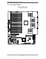
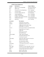
Page 43: ...1 9 Chassis CPU Fan Headers GLAN1 2 Gigabit Ethernet RJ45 Ports J12 IPMB Header of the IPMI module J13 PWR SMBus I2 C Connector J15 J16 Serial General Purpose Input Output Headers J17 Floppy Disk Drive Connector J19 SIMSO Slot J3P1 PWR Supply Fail LED JAR Alarm Rest Header JCOM1 JCOM2 COM1 Serial Port Header JD1 Onboard Speaker Power LED JF1 Front Panel Connector JIDE1 JIDE2 IDE Drive Compact Flas...

Page 44: ...nition 13 3 3V 1 3 3V 14 12V 2 3 3V 15 COM 3 COM 16 PS_ON 4 5V 17 COM 5 COM 18 COM 6 5V 19 COM 7 COM 20 Res NC 8 PWR_OK 21 5V 9 5VSB 22 5V 10 12V 23 5V 11 12V 24 COM 12 3 3V Reset Button Pin Definitions JF1 Pin Definition 3 Reset 4 Ground Power Button Pin Definitions JF1 Pin Definition 1 PW_ON 2 Ground Processor Power Connector JPW2 and JPW3 must also be con nected to the power supply to provide power...

Page 45: ... Pin Definition 7 Vcc 8 Ground NIC2 LED Pin Definitions JF1 Pin Definition 9 Vcc 10 Ground HDD LED Pin Definitions JF1 Pin Definition 13 Vcc 14 HD Active NIC2 JLAN2 LED The LED connections for JLAN2 are on pins 9 and 10 of JF1 Attach an LED cable to display network activ ity See the table on the right for pin definitions NIC1 LED Pin Definitions JF1 Pin Definition 11 Vcc 12 Ground NIC1 JLAN1 LED The LED c...

Page 46: ...he mouse port is above the keyboard port See the table on the right for pin definitions NMI Button The non maskable interrupt button header is located on pins 19 and 20 of JF1 Refer to the table on the right for pin definitions NMI Button Pin Definitions JF1 Pin Definition 19 Control 20 Ground Fan Header Pin Definitions FAN1 9 Pin Definition 1 Ground Black 2 12V Red 3 Tachometer 4 PWM Control PS 2 Keybo...

Page 47: ...e the VGA port on the I O backplane These ports accept RJ45 type cables Wake On Ring The Wake On Ring header is desig nated JWOR1 This function allows your computer to receive and be awakened by an incoming call when in the suspend state See the table on the right for pin definitions You must also have a WOR card and cable to use this feature Wake On Ring Pin Definitions JWOR1 Pin Definition 1 Ground...

Page 48: ...n Definitions USB USB0 1 Pin Definition USB2 3 4 Pin Definition 1 5V 1 5V 2 PO 2 PO 3 PO 3 PO 4 Ground 4 Ground 5 N A 5 Key Power LED Speaker On JD1 header pins 1 3 are for a power LED and pins 4 7 are for the speaker Close pins 4 7 with a jumper to use an external speaker If you wish to use the onboard speaker please close pins 6 7 See the table on the right for speaker pin definitions Power LED Spea...

Page 49: ...ight for pin definitions Alarm Reset Header Pin Definitions JAR Pin Setting Definition Pin 1 Ground Pin 2 5V Overheat LED Fan Fail JOH1 The JOH1 header is used to connect an LED to provide warning of chassis overheating This LED will blink to in dicate a fan failure Refer to the table on right for pin definitions Overheat LED Pin Definitions JOH1 Pin Definition 1 5vDC 2 OH Active OH Fan Fail LED States ...

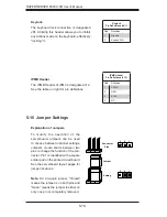
Page 50: ...er locations Note On a two pin jumper Closed means the jumper is on both pins and Open means the jumper is either on only one pin or completely removed Connector Pins Jumper Setting 3 2 1 3 2 1 Keylock The keyboard lock connection is designated JK1 Utilizing this header allows you to inhibit any actions made on the keyboard effectively locking it Keylock Pin Definitions JK1 Pin Definition 1 Ground 2...

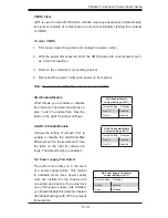
Page 51: ...or jumper settings VGA Enable Disable Jumper Settings JPG1 Jumper Setting Definition Pins 1 2 Enabled Pins 2 3 Disabled 3rd Power supply Fail Detect The system can notify you in the event of a power supply failure This feature is available when three power supply units are installed in the chassis with one acting as a backup If you only have one or two power supply units installed you should disabl...

Page 52: ...umping pins 1 2 will cause WD to reset the system if an application hangs Jumping pins 2 3 will generate a non maskable interrupt signal for the application that hangs See the table on the right for jumper settings Watch Dog must also be en abled in BIOS Note When enabled the user needs to write their own application software in order to disable the Watch Dog Timer Watch Dog Jumper Settings JWD Ju...

Page 53: ...Jumper Settings JP5 Jumper Setting Definition Open 130W for 2U Platform Closed 80W for 1U Platform CPU Power Select JP5 allows you to select the CPU power settings The default position is Open to support 130 W for 2U systems See the table on the right for jumper settings RAID Mode Jumper Settings JPS2 Jumper Setting Definition Closed MegaRAID Open Integrated RAID RAID Mode JPS2 allows you to switch ...

Page 54: ... Onboard Power LED is located at LE1 This LED Indicator is on when the system is on Be sure to unplug the power cable before removing or adding any components See the table on the right for more details Onboard PWR LED Indicator LE1 LED Color Definition Off System Off PWR cable not connected Green System On Green Flashing Quickly ACPI S1 State Green Flashing Slowly ACPI S3 STR State SAS Activity LE...

Page 55: ...tor s to your hard drive s Consult the documentation that came with your disk drive for details on actual jumper locations and settings for the hard disk drive Floppy Connector The floppy connector is located at J17 See the table below for pin definitions Floppy Drive Connector Pin Definitions J17 Pin Definition Pin Definition 1 Ground 2 FDHDIN 3 Ground 4 Reserved 5 Key 6 FDEDIN 7 Ground 8 Index 9 Grou...

Page 56: ... Key 21 DRQ3 22 Ground 23 I O Write 24 Ground 25 I O Read 26 Ground 27 IOCHRDY 28 BALE 29 DACK3 30 Ground 31 IRQ14 32 IOCS16 33 Addr1 34 Ground 35 Addr0 36 Addr2 37 Chip Select 0 38 Chip Select 1 39 Activity 40 Ground IDE Connectors There are two IDE Connectors JIDE1 Blue JIDE2 White on the serverboard JIDE1 is designated as the Primary IDE drive JIDE2 is designated as the Secondary IDE drive and ...

Page 57: ...o prevent damage to any printed circuit boards PCBs it is important to handle them very carefully The following measures are generally sufficient to protect your equipment from ESD damage Precautions Use a grounded wrist strap designed to prevent static discharge Touch a grounded metal object before removing any board from its antistatic bag Handle a board by its edges only do not touch its compone...

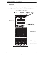
Page 58: ...stem Reset Main Power System LEDs Floppy Drive 5 25 Drive Bays 2 USB Ports 2x Power Supply Modules module on the right is a dummy Unpacking The serverboard is shipped in antistatic packaging to avoid static damage When unpacking the board make sure the person handling it is static protected ...

Page 59: ...er to the control panel side of the chassis The LEDs on the control panel inform you of system status see Figure 6 2 for details See Chapter 5 for details on JF1 Figure 6 2 Front Control Panel LEDs Power NIC1 HDD Power Fail Overheat Fan Fail Indicates power is being supplied to the system Indicates network activity on LAN port 1 Indicates IDE device and hard drive activity On the SC748TQ R1200 thi...

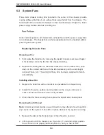
Page 60: ...tabs on the failed chassis fan On an exhaust fan push down on the colored tab then with the tab depressed pull the unit straight out see Figure 6 3 The wiring for these fans has been designed to detach automatically Installing a New Fan Replace the failed fan with an identical one available from Supermicro Install it in the same position and orientation as the one you removed A click can be heard ...

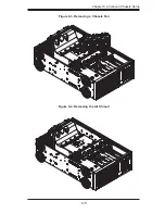
Page 61: ...Chapter 6 Advanced Chassis Setup 6 5 Figure 6 4 Removing the Air Shroud Figure 6 3 Removing a Chassis Fan ...

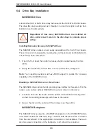
Page 62: ...ust remain in the server Insert the drive into the carrier with the printed circuit board side facing down so that the mounting holes align with those in the carrier Secure the drive to the carrier with four screws see Figure 6 5 SAS SATA Backplane The SAS SATA drives plug into a SAS SATA backplane on the CSE M35P mobile rack which houses the SAS drive bays The SAS data cables must be connected fr...

Page 63: ...A Drive in a Carrier Important Use extreme caution when working around the SAS SATA backplane Do not touch the backplane with any metal objects and make sure no ribbon cables touch the backplane or obstruct the airflow holes Figure 6 4 Removing a SAS SATA Drive Carrier ...

Page 64: ...e the DVD CD ROM into the bay and secure it to the chassis with the drive carrier screws you first removed Attach the power and data cables to the drive Replace the top left chassis cover and restore power to the system Adding an IDE or Floppy Drive Install an IDE or floppy into one of the removed empty drive carriers with the printed circuit board side toward the carrier so that the drive s mountin...

Page 65: ...n replaced Replacement units can be ordered directly from Supermicro The hot swap capability of the power supply modules allows you to replace the failed module without powering down the system Removing Replacing the Power Supply You do not need to shut down the system to replace a power supply unit The redundant feature will keep the system up and running while you replace the failed hot swap uni...

Page 66: ...odule Installing a New Power Supply Replace the failed module with another power supply module It must be the exact same Refer to Appendix C for the correct part number Push the new power supply unit into the power bay until you hear a click Plug the AC power cord back in 1 2 3 ...

Page 67: ...e right frame displays the key legend Above the key legend is an area reserved for a text message When an op tion is selected in the left frame it is highlighted in white Often a text message will accompany it Note the AMI BIOS has default text messages built in Supermicro retains the option to include omit or change any of these text messages The AMIBIOS Setup Utility uses a key based navigation ...

Page 68: ...u select this option the AMI BIOS will automatically display the status of processors System Memory This option allows the AMI BIOS to display the status of memory modules installed in the system System Time System Date Use this option to change the system time and date Highlight System Time or System Date using the arrow keys Enter new values through the keyboard Press the Tab key or the arrow ke...

Page 69: ...bled This option allows the user to set the ratio between the CPU Core Clock and the FSB frequency The default setting is 6 Hardware Prefetcher Available when supported by the OS and the CPU If set to Enabled the hardware prefetcher will prefetch streams of data and instructions from the main memory to the L2 cache in the forward or backward manner to improve CPU performance The options are Disabl...

Page 70: ...erwhelm the processor or damage the system during an attack Note For more information regarding hardware software support for this function please refer to Intel s and Microsoft s web sites Intel SpeedStep Technology Available when supported by the CPU TheEnhancedIntelSpeedStepTechnologyallowsthesystemtoautomaticallyadjust processor voltage and core frequency in an effort to reduce power consumpti...

Page 71: ... PIO Programmable I O Mode programs timing cycles between the IDE drive and the programmable IDE controller As the PIO mode increases the cycle time decreases The options are Auto 0 1 2 3 and 4 Select Auto to allow the AMI BIOS to automatically detect the PIO mode Use this value if the IDE disk drive support cannot be determined Select 0 to allow the AMI BIOS to use PIO mode 0 It has a data transf...

Page 72: ... UDMA2 to allow the BIOS to use Ultra DMA mode 2 It has a data transfer rate of 33 3 MBs Select UDMA3 to allow the BIOS to use Ultra DMA mode 3 It has a data transfer rate of 66 6 MBs Select UDMA4 to allow the BIOS to use Ultra DMA mode 4 It has a data transfer rate of 100 MBs The options are Auto SWDMAn MWDMAn and UDMAn S M A R T For Hard disk drives Self Monitoring Analysis and Reporting Technol...

Page 73: ...ice installed on a PCI bus The default setting is 64 Select 32 to set the PCI latency to 32 PCI clock cycles Select 64 to set the PCI latency to 64 PCI clock cycles Select 96 to set the PCI latency to 96 PCI clock cycles Select 128 to set the PCI latency to 128 PCI clock cycles Select 160 to set the PCI latency to 160 PCI clock cycles Select 192 to set the PCI latency to 192 PCI clock cycles Selec...

Page 74: ...es The options are Disabled 16K 32K 64K Super IO Configuration Submenu Onboard Floppy Controller Select Enabled to enable the onboard floppy controller The options are Enabled and Disabled Serial Port1 Address Serial Port2 Address This option specifies the base I O port addresses and the Interrupt Request ad dresses for Serial Port 1 and Serial Port 2 Select Disabled to prevent the serial port from a...

Page 75: ...t correctable memory errors found on FBD memory modules Select Enabled to use Patrol Scrubbing a background ECC memory correction activity initiated by the northbridge to find and correct memory errors by scanning all memory modules doing simulated READs while checking for ECC errors When an ECC error is detected during this process it is logged as a Patrol error A correctable error is corrected an...

Page 76: ...et to 0 all memory modules installed on Branch 1 must support Lockstep Operation The options are 0 and 1 Boot Graphics Adapter Priority This feature allows the user to decide which graphics controller to be used as the primary boot device The options are Auto and Onboard VGA Read Completion Coalescing This feature allows you to enable the PCI Express Compliance Mode The options are Auto Disabled a...

Page 77: ...allows the user to set the maximum PCI speed for the PCI slot specified Select Auto to allow the BIOS to automatically detect the capability of the device installed on the bus The options for Slot 1 are Auto 33 MHz PCI 66 MHz PCI 66 MHz PCI X 100 MHz PCI X and 133 MHz PCI X The options for Slot 2 are Auto 66 MHz PCI 100 MHz PCI X and 133 MHz PCI X I O Port Decode This option allows the user to sele...

Page 78: ...Legacy USB Support Select Enabled to enable USB Legacy support Disable legacy support if there are no USB devices installed in the system The options are Disabled Enabled and Auto USB 2 0 Controller Mode This setting allows you to configure the USB 2 0 Controller Mode The options are Hi Speed 480 Mbps and Full Speed 12Mbps BIOS EHCI Hand Off Select Enabled to halt the operation of the ECHI Host con...

Page 79: ...D and CD ROM APCI Configuration This item allows the user to enable or disable the ACPI support for the operating system Advanced ACPI Configuration Use this feature to configure advanced ACPI options Select Yes if the operating system supports ACPI Select No if the operating system does not support ACPI ACPI Version Features Select Yes to allow the RSDP pointers to point to the Fixed System Descript...

Page 80: ... Mode If set to Suspend video will go into the Suspend Mode when the system is in the Suspend or Standby Mode The options are Disabled and Suspend Hard Disk Power Down Mode If set to Suspend the onboard hard disk drives will go into the Suspend Mode when the system is in the Suspend or Standby Mode The options are Disabled and Suspend Suspend Time Out If set to Disabled the system will not go into...

Page 81: ...modem receives an incoming call The options are Enabled and Disabled Resume On PME Select Enabled to allow PME to generate a wake event The options are Enabled and Disabled Resume On RTC Alarm Select Enabled to use the Real Time Clock RTC to set the timer for the system to be awakened The options are Enabled and Disabled ...

Page 82: ...e option is set to 4 pin the fan speed will be controlled by Pulse Width Modulation PWM Select 3 pin if your chassis came with 3 pin fan headers Select 4 pin if your chassis came with 4 pin fan headers Select Workstation if your system is used as a Workstation Select Server if your system is used as a Server Select Disable to disable the fan speed control function to allow the onboard fans to run ...

Page 83: ...llow the instruc tions given on the screen to select the MPS Revision Number The options are 1 1 and 1 4 PCI Express Configuration This section allows the user to configure the PCI Express slots Active State Power Management Select Enabled to activate the function of power management for signal transac tions between the PCI Express L0 and L1 Links The options are Enabled and Disabled ...

Page 84: ...direction The options are COM1 and COM2 Base Address IRQ This feature allows the user to set the Base Address and IRQ settings for COM1 or COM2 The default setting for COM1 is 3F8h 4 The default setting for COM2 is 2F8h 8 Serial Port Mode This feature allows the user to set the serial port mode for Console Redirection The options are 115200 8 N 1 57600 8 N 1 38400 8 N 1 19200 8 N 1 and 9600 8 N 1 ...

Page 85: ...UTF8 Combination Key support for the ANSI VT100 Terminals The options are Enabled and Disabled Sredir Memory Display Delay This feature allows the user to decide how many seconds the BIOS will wait before memory information is displayed The options are No Delay Delay 1 Sec Delay 2 Sec and Delay 4 Sec Trusted Computing TCG TPM Support This feature allows the user to enable or disable TPM TCG TPM 1 ...

Page 86: ...w the computer system to display the POST messages Select Enabled to allow the computer system to display the OEM logo Add On ROM Display Mode This option allows the BIOS to display add on ROM read only memory mes sages Select Force BIOS to display a third party BIOS during system boot Select Keep Current to display the current BIOS information during system boot Bootup Num Lock This option allows...

Page 87: ...his feature allows the user to select which graphics controller to be used as the primary boot device The options are Auto and Onboard VGA Watch Dog Timer If enabled this option will automatically reset the system if the system is not active for more than 5 minutes The options are Enabled and Disabled Boot Device Priority This feature allows the user to specify the sequence of priority for the Boo...

Page 88: ...or the first Removable Drive and the second Removable Drive The options are 1st Floppy Drive USB Pepper Virtual Disc 1 2nd Drive and Disabled CD DVD Drives This feature allows the user to specify the boot sequence from available CD DVD Drives 1st Drive 2nd Drive This option allows the user to specify the boot sequence for the First CD DVD Drive and the Second CD DVD Drive The options are CD DVD PS ...

Page 89: ...d Set to Always to allow the system to perform a password check when the BIOS Setup is invoked or when the system boots up Boot Sector Virus Protection This option is near the bottom of the Security Setup screen Select Disabled to deactivate the Boot Sector Virus Protection Select Enabled to enable boot sector protection When Enabled the AMIBOIS displays a warning when any program or virus issues ...

Page 90: ...Exit Select this option to quit the BIOS Setup without making any permanent changes to the system configuration and reboot the computer Select Discard Changes and Exit from the Exit menu and press Enter Discarding Changes Select this option and press Enter to discard all the changes and return to the AMIBIOS Utility Program Load Optimal Defaults To set this feature select Load Optimal Defaults from...

Page 91: ...OS 7 25 Load Fail Safe Defaults To set this feature select Load Fail Safe Defaults from the Exit menu and press Enter The Fail Safe settings are designed for maximum system stability but not for maximum performance ...

Page 92: ...7 26 SUPERSERVER 8045C 3R User s Manual Notes ...

Page 93: ...rd Controller Failed Keyboard controller failed test May require replacing keyboard controller Keyboard locked Unlock key switch Unlock the system to proceed Monitor type does not match CMOS Run SETUP Monitor type not correctly identified in Setup Shadow Ram Failed at offset nnnn Shadow RAM failed at offset nnnn of the 64k block at which the error was de tected System RAM Failed at offset nnnn Syst...

Page 94: ...fully POST loads default values and offers to run Setup If the failure was caused by incorrect values and they are not corrected the next boot will likely fail On systems with control of wait states improper Setup settings can also terminate POST and cause this error on the next boot Run Setup and verify that the waitstate configuration is correct This error is cleared the next time the system is b...

Page 95: ...ess Conflict Address conflict for specified device Allocation Error for device Run ISA or EISA Configuration Utility to resolve resource conflict for the specified device CD ROM Drive CD ROM Drive identified Entering SETUP Starting Setup program Failing Bits nnnn The hex number nnnn is a map of the bits at the RAM address which failed the memory test Each 1 one in the map indicates a failed bit See error...

Page 96: ...annot be located on either drive A or drive C Enter Setup and see if fixed disk and drive A are properly identified Parity Check 1 nnnn Parity error found in the system bus BIOS attempts to locate the address and display it on the screen If it cannot locate the address it displays Parity is a method for checking errors in binary data A parity error indicates that some data has been corrupted Parity ...

Page 97: ... devices have the Configuration Request bit set in the LCT Run an I2O Configuration Utility e g the SAC utility System BIOS shadowed System BIOS copied to shadow RAM UMB upper limit segment address nnnn Displays the address nnnn of the upper limit of Upper Memory Blocks indicating released segments of the BIOS which can be reclaimed by a virtual memory man ager Video BIOS shadowed Video BIOS success...

Page 98: ...A 6 SUPERSERVER 8045C 3R User s Manual Notes ...
Page 99: ...l write the error to port 80h attempt to initialize video and write the error in the top left corner of the screen The following is a list of codes that may be written to port 80h POST Code Description 01h IPMI Initialization 02h Verify Real Mode 03h Disable Non Maskable Interrupt NMI 04h Get CPU type 06h Initialize system hardware 07h Disable shadow and execute code from the ROM 08h Initialize ch...

Page 100: ...ncy 33h Initialize Phoenix Dispatch Manager 36h Warm start shut down 38h Shadow system BIOS ROM 3Ah Auto size cache 3Ch Advanced configuration of chipset registers 3Dh Load alternate registers with CMOS values 41h Initialize extended memory for RomPilot optional 42h Initialize interrupt vectors 45h POST device initialization 46h 2 1 2 3 Check ROM copyright notice 48h Check video configuration agains...

Page 101: ...r I O ports and IRQs optional 81h Late POST device initialization 82h Detect and install external RS232 ports 83h Configure non MCD IDE controllers 84h Detect and install external parallel ports 85h Initialize PC compatible PnP ISA devices 86h Re initialize onboard I O ports 87h Configure Motherboard Configurable Devices optional 88h Initialize BIOS Data Area 89h Enable Non Maskable Interrupts NMIs 8...

Page 102: ...e QuietBoot optional B6h Check password optional B7h Initialize ACPI BIOS and PPM Structures B9h Prepare Boot BAh Initialize SMBIOS BCh Clear parity checkers BDh Display MultiBoot menu BEh Clear screen optional BFh Check virus and backup reminders C0h Try to boot with INT 19 C1h Initialize POST Error Manager PEM C2h Initialize error logging C3h Initialize error display function C4h Initialize syst...

Page 103: ...rrupt vectors F1h Initialize Run Time Clock F2h Initialize video F3h Initialize System Management Manager F4h Output one beep F5h Clear Huge Segment F6h Boot to Mini DOS F7h Boot to Full DOS Note If the BIOS detects errors on 2C 2E or 30 base 512K RAM error it dis plays an additional word bitmap xxxx indicating the address line or bits that have failed For example 2C 0002 means address line 1 bit ...

Page 104: ...B 6 SUPERSERVER 8045C 3R User s Manual Notes ...
Page 105: ...ns you must first use the Intel ESB2 SATA RAID Utility program to configure the RAID Level that you desire before installing the Windows XP 2000 2003 operating system and other software drivers The necessary drivers are all included on the Supermicro CD that came packaged with your motherboard Note that the current version of the ESB2 SATA RAID Utility can only support Windows XP 2000 2003 Operating...

Page 106: ...e and generate a virtual RAID 0 RAID 1 RAID 10 and RAID 5 sets It also allows you the change the HDD partition size without any data Configuring BIOS Settings Press the Del key during system bootup to enter the BIOS Setup Utility Note If it is the first time powering on the system we recommend you load the Optimized Default Settings If you have already done so please skip to Step 3 Use the arrow key...

Page 107: ...er Then select En abled Scroll down to Exit Select Save and Exit from the Exit menu Press the Enter key to save the changes and exit the BIOS Once you ve exited the BIOS Utility the system will re boot During the system boot up press the Ctrl and I keys simultaneously to run the Intel RAID Configuration Utility when prompted by the following message Press Ctrl I for the Intel RAID Configuration Util...

Page 108: ...eys to select RAID 0 Stripe and hit Enter When the Disks item is highlighted press Enter to select the HDD to configure as RAID The following pop up screen displays 2 3 4 Use the Up Arrow Down Arrow keys to highlight a drive and press Space to select it A triangle appears to confirm the selection of the drive Use the Up Arrow Down Arrow keys to select the stripe size rang ing from 4 KB to 128 KB for...

Page 109: ... a name for the RAID 1 set and press the Tab key or the Enter key to go to the next field You can use the Esc key to select the previous menu When RAID Level item is highlighted press the Up Arrow Down Arrow keys to select RAID 1 Mirror and hit Enter When the Capacity item is highlighted enter your RAID volume capacity and hit Enter The default setting is the maximum capacity allowed Press Enter wi...

Page 110: ...Arrow keys to select the stripe size from 4 KB to 128 KB for your RAID 10 and hit Enter The default setting is 64 KB Note For a server please use a lower stripe size and for a multimedia system use a higher stripe size When the RAID Volume Capacity item is highlighted enter your RAID volume capacity and hit Enter The default setting is the maximum capacity allowed Press Enter when the Create Volum...

Page 111: ... The following pop up screen see note on page C 3 displays 2 3 4 Use the Up Arrow Down Arrow keys to highlight a drive and press Space to select it A triangle appears to confirm the selection of the drive Use the Up Arrow Down Arrow keys to select the stripe size rang ing from 4 KB to 128 KB for the RAID 5 array and hit Enter Note For a server please use a lower stripe size and for a multimedia sys...

Page 112: ...e Volume menu 8 9 Warning Be sure to back up your data before deleting a RAID set You will lose all data on the disk drives when deleting a RAID set From the main menu select Delete RAID Volume and press Enter Use the Up Arrow Down Arrow keys to select the RAID set you want to delete and press Del A Warning message displays When asked Are you sure you want to delete this volume Y N press Y to dele...

Page 113: ...d delete the internal RAID structure on the drive Resetting to Non RAID and Resetting a RAID HDD Use the Up Arrow Down Arrow keys to highlight the RAID set drive to reset and press Space to select Press Enter to reset the RAID set drive A Warning message displays Press Y to reset the drive or N to go back to the main menu Exiting the Intel Matrix Storage Manager Utility From the main menu select E...

Page 114: ...r Choose the Intel ESB2 SATA RAID controller from the list indicated in the XP 2000 2003 Setup Screen and press the Enter key Press the Enter key to continue the installation process If you need to specify any additional devices to be installed do so at this time Once all devices are specified press the Enter key to continue with the installation From the Windows XP 2000 2003 Setup screen press the...

Page 115: ...D ECC DDR2 667 533 SDRAM Note See the memory section in Chapter 5 for details SAS Controller Onboard LSI 1068E controller for SAS drives RAID 0 1 and 10 support Drive Bays Five hot swap drive bays to house six 5 standard SAS SATA drives Peripheral Drives Bays One floppy drive Two 5 25 drive bays Expansion Slots Supports the use of seven standard size expansion cards one PCI E x8 in a x16 slot one P...

Page 116: ...Voltages 3 3V 20A 5V 20A 12V 100A 12V 0 6A 5Vsb 4A Power Supply Efficiency Rating 91 peak Operating Environment Operating Temperature 10º to 35º C 50º to 95º F Non Operating Temperature 40º to 70º C 40º to 158º F Operating Relative Humidity 8 to 90 non condensing Non Operating Relative Humidity 5 to 95 non condensing Regulatory Compliance Electromagnetic Emissions FCC Class A EN 55022 Class A EN 61...

Page 117: ...anagement Practices Regulations for Perchlorate Materials This Perchlorate warning applies only to products containing CR Manganese Dioxide Lithium coin cells Perchlorate Material special handling may apply See www dtsc ca gov hazardouswaste perchlorate ...

Page 118: ...4 SUPERSERVER 8045C 3R User s Manual Notes ...
Reviews: