Supermicro SuperServer 7049P-TR User Manual Download Page 52

SuperServer 7049P-TR(T) User's Manual

52

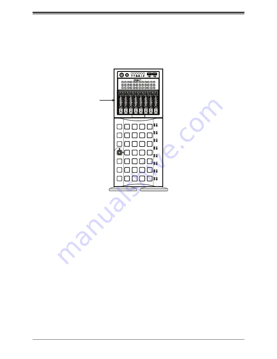
Additional Storage Drives in a Mobile Rack

The chassis accepts a Supermicro mobile rack (pn CSE-M28SABP) in place of two 5.25" 
bays. This adds eight hot-swap 2.5" SAS or SATA drives. An optional expansion card and 
cables are also required.

Figure 3-14. Chassis with a Mobile Rack Installed

Installing the Mobile Rack 

1. 

Remove two adjacent trays from the drive bays.

2. Remove the drive tray rails. 

Mobile Rack

Summary of Contents for SuperServer 7049P-TR

Page 1: ...USER S MANUAL Revision 1 0a SuperServer 7049P TR 7049P TRT...

Page 2: ...operated in a commercial environment This equipment generates uses and can radiate radio frequency energy and if not installed and used in accordance with the manufacturer s instruction manual may cau...

Page 3: ...s utilities and the user s manual for your server Supermicro product manuals http www supermicro com support manuals Product drivers and utilities ftp ftp supermicro com Product safety info http www s...

Page 4: ...Mounting 17 Choosing a Setup Location 17 Rack Precautions 17 Server Precautions 18 Rack Mounting Considerations 18 Ambient Operating Temperature 18 Airflow 18 Mechanical Loading 18 Circuit Overloadin...

Page 5: ...et for Installation 37 Installing the Processor Heatsink Module PHM 38 Connecting an HFI Carrier Card 39 Removing the Processor Heatsink Module from the Motherboard 40 Memory 41 Memory Support 41 DIMM...

Page 6: ...ion 72 Installing the Windows OS for a RAID System 72 Installing Windows to a Non RAID System 72 5 2 Driver Installation 73 5 3 SuperDoctor 5 74 5 4 IPMI 75 Chapter 6 BIOS 6 1 Introduction 76 Starting...

Page 7: ...ddress Super Micro Computer B V Het Sterrenbeeld 28 5215 ML s Hertogenbosch The Netherlands Tel 31 0 73 6400390 Fax 31 0 73 6416525 Email sales supermicro nl General Information support supermicro nl...

Page 8: ...X11DPi N T motherboard and the SC745BAC R1K28B chassis The server offers two network ports The 7049P TR model supports 1 Gbps The 7049P TRT model supports 10 Gbps In addition to the motherboard and ch...

Page 9: ...3 MHz modules in 16 slots up to 256 GB size Chipset Intel C620 Series Expansion Slots Six PCI Express 3 0 slots four x16 and two x8 Input Output Network Two LAN ports 7049P TR model 1 Gbps or 7049P TR...

Page 10: ...icates network activity on LAN port 2 when flashing 7 Information LED See table below for details 8 Power Fail LED This LED flashes to indicate one of the redundant power supply modules has failed The...

Page 11: ...w Front Chassis Features Item Feature Description 1 Control Panel Front control panel with LEDs and buttons see preceding page 2 Peripheral Drive Bays Three 5 25 bays for optional peripherals such as...

Page 12: ...undant 1280 W Platinum Level Power Supplies 2 I O Back Panel Rear I O ports see Section 4 3 3 Fans Two 8 cm exhaust fans 4 Expansion Slots Six PCI Express expansion card slots Figure 1 3 Chassis Rear...

Page 13: ...A4 3 0 USB 7 8 3 0 USB 6 USB 2 3 COM2 CPU1 SLOT1 PCI E 3 0 X8 CPU1 SLOT2 PCI E 3 0 X16 CPU1 SLOT3 PCI E 3 0 X8 CPU2 SLOT4 PCI E 3 0 X16 CPU2 SLOT5 PCI E 3 0 X16 CPU2 SLOT6 PCI E 3 0 X16 UID LAN2 LAN1...

Page 14: ...PMB1 4 pin BMC External I2 C header for an IPMI supported card JL1 Chassis Intrusion header JM2_1 PCIe M 2 slot JNVI2 C1 JNVI2 C2 NVMe I2 C headers used for PCIe hot plug SMBus clock and data connecti...

Page 15: ...USB4 5 Back panel USB 3 0 Ports USB6 Type A USB 3 0 Header USB7 8 Front Accessible USB 3 0 Header VGA VGA Port LED Description State Status LE1 UID Unit Identifier LED Solid Blue Unit identified LE2 O...

Page 16: ...PCI E X8 PCI E X16 G3 LANE REVERSE DMI3 PCI E X16 PCI E X8 G3 PCI E X8 G3 2 I M D 3 I M D DDR4 DDR4 PCI E X8 LAN 10G 1G SLOT 4 SLOT 5 PCI E X16 PCI E X16 SLOT 6 PCI E X16 PCI E X16 G3 PCI E X16 G3 PCI...

Page 17: ...ields are generated Leave at least 25 inches clearance in front of the rack to open the front door completely Leave approximately 30 inches of clearance in the back of the rack to allow for sufficient...

Page 18: ...s and voltage spikes and to keep your system operating in case of a power failure Allow any drives and power supply modules to cool before touching them When not servicing always keep the front door o...

Page 19: ...connections other than the direct connections to the branch circuit i e the use of power strips etc To prevent bodily injury when mounting or servicing this unit in a rack you must take special preca...

Page 20: ...cover lock to the right and push chassis cover forward 3 Lift the chassis top cover off the chassis Figure 2 1 Remove Feet and Chassis Top Cover Tower Top Cover Chassis Feet Chassis Cover Lock Removi...

Page 21: ...ck you are using Identifying the Rails The optional rackmount kit includes two rack rail assemblies one for each side Each of these assemblies consist of several sections an inner fixed rail that secu...

Page 22: ...andles to the front sides of the chassis with three screws each 2 Position the inner rails along the side of the chassis making sure the screw holes line up 3 Screw the rail securely to the side of th...

Page 23: ...re specific for the left and right rails 2 Secure the front short bracket onto the outer rail with M5 screws 3 Mount the rear long bracket onto the outer rail at the approximate position to fit your r...

Page 24: ...the rear of the inner chassis rails with the front of the outer rack rails and slide the inner rails into the outer rails until the server is completely in the rack 3 Insert and tighten the thumbscrew...

Page 25: ...rack without assistance Be sure to have sufficient assistance supporting the chassis when removing it from the rack Use a lift 1 Pull the chassis forward out the front of the rack until it stops 2 Fin...

Page 26: ...in a rack rotate the module that contains the control panel and the three drive trays 1 in Figure 2 6 90 degrees Note that two of the 5 25 drives may be replaced by a mobile rack containing eight 2 5...

Page 27: ...release lever to unlock the module Module Release Lever Control Panel Drive Module in Rack Mount Orientation 3 4 Grasp the edges of the module and pull it from the chassis 5 Rotate the module 90 degre...

Page 28: ...t components require that power first be removed from the system Please follow the procedures given in each section 3 1 Removing Power Use the following procedure to ensure that power has been removed...

Page 29: ...movable side cover top if rack mounted which allows access to the internal components Removing the Side Cover 1 Locate the latch on the cover depress where it says push then lift the latch to release...

Page 30: ...ould be assembled together first to form the Processor Heatsink Module PHM and then install the entire PHM into the CPU socket When receiving a motherboard without a processor pre installed make sure...

Page 31: ...embly contains 1 the Intel SKX F CPU 2 the narrow processor clip 3 the dust cover and 4 the CPU socket 3 Dust Cover 4 CPU Socket 1 SKX F CPU Note Be sure to cover the CPU socket with the dust cover wh...

Page 32: ...SuperServer 7049P TR T User s Manual 32 Figure 3 3 Heatsink SNK P0068PS Heatsinks The 7049P TR T server uses this heatsink design for each processor...

Page 33: ...the Processor Heatsink Module PHM The Processor Heatsink Module PHM contains 1 a heatsink 2 a narrow processor clip and 3 the SKX F processor 1 Heatsink 2 Narrow processor clip 3 SKX F Processor Bott...

Page 34: ...er position on the processor clip and carefully insert the CPU into the processor clip Slide notch B of the CPU into tab B of the processor clip and slide notch C of the CPU into tab C of the processo...

Page 35: ...ip CPU Upside Down w CPU LGA Lands up CPU Heatsink Package Upside Down B B Align Notch B of the CPU and Notch B of the Processor Clip Processor Package Assembly for the F Model Processors with CPU mou...

Page 36: ...set of mounting clips and a hole at the diagonal corner of the of the processor package assembly b in the drawing 4 With the underside of heatsink and the underside of the processor package assembly f...

Page 37: ...er a socket bracket the CPU socket P0 and a back plate CPU Socket with Dust Cover On Removing the Dust Cover from the CPU Socket Remove the dust cover from the CPU socket exposing the socket pins as s...

Page 38: ...diagonal corners of the PHM onto the two guide posts on the socket bracket and carefully drop the PHM onto the socket 4 Use a T30 Torx bit screwdriver to install four screws into the mounting holes o...

Page 39: ...otherboard 3 Connect the HFI connector on the HFI sideband cable to the JHFI1 header 4 Connect the other end of the HFI cable to the connector marked A on the HFI card as shown below 5 Connect the the...

Page 40: ...ver loosen and remove the screws on the PHM from the socket starting with the screw marked 4 in the sequence of 4 3 2 1 2 Pull up the PHM while releasing the small snap tabs on two corners of the sock...

Page 41: ...same motherboard will result in reduced memory performance Check the Supermicro website for possible updates to memory support DIMM Module Population Configuration For optimal memory performance follo...

Page 42: ...4RX4 3DS LRDIMM Raw Cards A B 8RX4 General Population Requirements DIMM Mixing Rules All DIMMs must be DDR4 X4 and X8 DIMMs can be mixed in the same channel Mixing of LRDIMMs and RDIMMs is not allowed...

Page 43: ...lated first Caution Exercise caution when installing or removing memory modules to prevent damage to the DIMMs or slots Installing Memory 1 Remove power from the system as described in Section 3 1 2 S...

Page 44: ...supports PCIe 3 0 X4 32 Gb s SSD cards in the 2280 and 22110 form factors A Holder B Holder Mount C Card Holder Mount Turn 90 degrees to lock Locked position with M 2 card Locked position Locked posit...

Page 45: ...lacing the Battery Begin by removing power from the system as described in section 3 1 1 Push aside the small clamp that covers the edge of the battery When the battery is released lift it out of the...

Page 46: ...rack that houses eight hot swap 2 5 drives Additional cables are also required Note Enterprise level hard disk drives are recommended for use in Supermicro chassis and servers For information on recom...

Page 47: ...he release button on the drive carrier This extends the drive carrier handle 3 Use the handle to pull the carrier out of the chassis 4 Remove the dummy drive from the carrier Figure 3 8 Removing the D...

Page 48: ...with the printed circuit board side facing downward and so that the mounting holes in the drive align with those in the drive carrier 3 Secure the hard drive to the carrier with the screws included wi...

Page 49: ...s to suit the user s needs Up to three 5 25 peripheral drives such as a DVD drive One or two additional fixed SATA SAS or solid state drives in a single tray A mobile rack with eight additional 2 5 ho...

Page 50: ...re the drive to the tray with four screws from the bottom For one or two 2 5 drives install the drives into the special purpose bracket then secure the bracket to drive tray with screws through the bo...

Page 51: ...Replace the chassis cover and power up the system Side Rails Drive Tray Figure 3 13 Removing Rails from the Drive Tray Installing a 5 25 Peripheral Device An optional peripheral device such as a DVD d...

Page 52: ...ile rack pn CSE M28SABP in place of two 5 25 bays This adds eight hot swap 2 5 SAS or SATA drives An optional expansion card and cables are also required Figure 3 14 Chassis with a Mobile Rack Install...

Page 53: ...re 3 15 Mobile Rack with Drive Tray Rails Rail 3 Install a drive tray rail onto each side of the mobile rack Make sure the arrow on the rail points toward the front of the chassis 4 Slide the mobile r...

Page 54: ...nsion Card 1 Power down the system and remove the cover 2 In the rear of the chassis push on PCI shield lock then lift the lock 3 Remove the screw holding the PCI shield in place and remove the shield...

Page 55: ...supply module also has a cooling fan Chassis Fans Under normal operation all three chassis fans and both exhaust fans run continuously They can be replaced without powering down the system hot swap R...

Page 56: ...nks Installing the Air Shroud The air shroud fits behind the two fans closest to the power supply Align the pins and press the air shroud into the chassis It should click into place Figure 3 19 Instal...

Page 57: ...swap capability of the power supply modules allows you to replace the failed module without powering down the system Replacement units can be ordered directly from Supermicro see contact information i...

Page 58: ...er opening the left side Replacing the Power Supply You do not need to shut down the system to replace a power supply module 1 Unplug the AC power cord from the failed power supply module 2 Push the r...

Page 59: ...g is included with the power supply One 24 pin Primary ATX Power JPWR3 Two 8 pin Processor Power JPWR1 JPWR2 Main ATX Power Connector The primary power connector JPWR3 meets the ATX SSI EPS 24 pin spe...

Page 60: ...4 PWM Control I SATA 3 0 and S SATA 3 0 Ports SATA is supported on the X11DPi N T motherboard by three iPass connectors and two SATA powered ports The powered ports S SATA4 S SATA5 are yellow connecto...

Page 61: ...d in creating optional advanced NVMe RAID configurations SGPIO Header The T SGPIO3 Serial General Purpose Input Output header is used to communicate with the enclosure management chip on the backplane...

Page 62: ...ock 4 No Connection Chassis Intrusion A chassis Intrusion header is located at JL1 on the motherboard Attach the appropriate cable from the chassis to alert you when the chassis is opened Chassis Intr...

Page 63: ...Supermicro complete system with a proprietary NVMe add on card and cable installed NVMe SMBus Header Pin Definitions Pin Definition 1 Data 2 Ground 3 Clock 4 VICCIO NVMe Connectors NVMe I2 C headers u...

Page 64: ...Data signal Ground Key Power On LED Control signal HDD LED Activity signal NIC1 LED Ground NIC2 LED Ground OH Fan Fail LED Ground Power Fail LED Ground Ground Ground 2 1 20 19 Power Button Pin Defini...

Page 65: ...7 Blue LED 8 OH Fan Fail LED LAN1 LAN2 LED Pin Definitions JF1 Pin Definition 9 NIC2 Activity LED 10 NIC2 Link LED 11 NIC1 Activity LED 12 NIC1 Link LED NIC1 NIC2 LAN1 LAN2 The NIC Network Interface...

Page 66: ...les The data cables in the system have been carefully routed to maintain airflow efficiency If you disconnect any of these cables take care to re route them as they were originally when reconnecting t...

Page 67: ...he onboard headers can be used to provide front side USB access with a cable not included IPMI Port A LAN port is a dedicated connection for IPMI Ethernet Ports Two Ethernet ports LAN1 LAN2 X11DPi NT...

Page 68: ...Connector Pins Jumper Setting 3 2 1 3 2 1 CMOS Clear JBT1 is used to clear CMOS which will also clear any passwords Instead of pins this jumper consists of contact pads to prevent accidentally cleari...

Page 69: ...power operation and management In the single operation mode online upgrade will be available via Recovery mode See the table below for jumper settings Manufacturer Mode Jumper Settings Jumper Setting...

Page 70: ...ide of the LAN port may be green amber or off indicating the speed of the connection LAN Link Indicator LED Settings LED Color Definition Off No Connection 10 or 100 Mbps Green 10 Gbps 7049P TRT only...

Page 71: ...this LED is on the system is on Be sure to turn off the system and unplug the power cord before removing or installing components Onboard Power LED Indicator LED Color Definition Off System Off power...

Page 72: ...port on the system Note for older legacy OS s please use a method to slipstream the drivers 3 Select the partition on the drive in which to install Windows 4 Browse the USB folder for the proper driv...

Page 73: ...er option is to go to the Supermicro website at http www supermicro com products Find the product page for your motherboard here where you may download individual drivers and utilities to your hard dr...

Page 74: ...nagement Protocol SNMP SuperDoctor 5 comes in local and remote management versions and can be used with Nagios to maximize your system monitoring needs With SuperDoctor 5 Management Server SSM Server...

Page 75: ...orm Management Interface IPMI IPMI is used to provide remote access monitoring and management There are several BIOS settings that are related to IPMI For general documentation and information on IPMI...

Page 76: ...an option is selected it is highlighted in white Settings printed in Bold are the default values In the left frame a indicates a submenu Highlighting such an item and pressing the Enter key opens the...

Page 77: ...rd Press the Tab key or the arrow keys to move between fields The date must be entered in MM DD YYYY format The time is entered in HH MM SS format Note The time is in the 24 hour format For example 5...

Page 78: ...Configuration Quiet Boot Use this feature to select the screen between displaying POST messages or the OEM logo at bootup Select Disabled to display the POST messages Select Enabled to display the OE...

Page 79: ...e try Boot When EFI Expansible Firmware Interface Boot is selected the system BIOS will automatically reboot the system from an EFI boot device after an initial boot failure Select Legacy Boot to allo...

Page 80: ...lect Enable to enable Execute Disable Bit support which will allow the processor to designate areas in the system memory where an application code can execute and where it cannot thus preventing a wor...

Page 81: ...e the DCU Data Cache Unit streamer prefetcher will prefetch data streams from the cache memory to the DCU Data Cache Unit to speed up data accessing and processing for CPU performance enhancement The...

Page 82: ...ores to run faster than the frequency specified by the manufacturer The options are Disable and Enable Hardware PM Power Management State Control Hardware P States If this feature is set to Disable ha...

Page 83: ...he system to malfunc tion North Bridge This feature allows the user to configure the settings for the Intel North Bridge UPI Ultra Path Interconnect Configuration This section displays the following U...

Page 84: ...figuration Enforce POR Select POR to enforce POR restrictions for DDR4 memory frequency and voltage programming The options are POR and Disable Memory Frequency Use this feature to set the maximum mem...

Page 85: ...to optimize memory performance The options are Enable and Disable Note This item will not be available when memory mirror mode is enabled Memory Correctable Error Threshold Use this item to enter the...

Page 86: ...y the user The options are x4x4x4x4 x4x4x8 x8x4x4 x8x8 x16 and Auto IOU1 IIO PCIe Br2 This item configures the PCI E Bifuraction setting for a PCI E port specified by the user The options are x4x4x4x4...

Page 87: ...will allow the hints to be sent to help facilitate and optimize the processing of certain transactions in the system memory The options are Enable and Disable Relaxed Ordering Select Enable to enable...

Page 88: ...e options are Enable and Disable Coherency Support Non Isoch Select Enable for the Non Iscoh VT d engine to pass through DMA Direct Memory Access to enhance system performance The options are Enable a...

Page 89: ...ed Port 60 64 Emulation Select Enabled for I O port 60h 64h emulation support which in turn will provide complete legacy USB keyboard support for the operating systems that do not support legacy USB d...

Page 90: ...ide which controller should be used for system boot The options are None SATA Controller sSATA Controller and Both Aggressive Link Power Management When this item is set to Enabled the SATA AHCI contr...

Page 91: ...The options are Enable and Disable SATA sSATA RAID Boot Select Available when the item Configure SATA as is set to RAID This feature allows the user to decide which controller should be used for syste...

Page 92: ...are Enabled and Disabled SR IOV Support Available if the system supports Single Root Virtualization Select Enabled for Single Root IO Virtualization support The options are Enabled and Disabled MMIOH...

Page 93: ...Select EFI to allow the user to boot the computer using an EFI Expansible Firmware Interface device installed on the PCI E slot specified by the user Select Legacy to allow the user to boot the comput...

Page 94: ...ns are Enabled and Disabled PXE Boot Wait Time Use this feature to select the wait time to press the ESC key to abort the PXE boot The default is 0 Media Detect Time Use this feature to select the wai...

Page 95: ...F8h IRQ 3 4 5 6 7 9 10 11 12 IO 2F8h IRQ 3 4 5 6 7 9 10 11 12 IO 3E8h IRQ 3 4 5 6 7 9 10 11 12 and IO 2E8h IRQ 3 4 5 6 7 9 10 11 12 Serial Port 2 Attribute Select SOL to use COM Port 2 as a Serial_Ove...

Page 96: ...be sent with your data bits The options are None Even Odd Mark and Space Stop Bits A stop bit indicates the end of a serial data packet Select 1 Stop Bit for standard serial data communication Select...

Page 97: ...uter will exchange data with the client computer which is the remote computer used by the user Terminal Type Use this feature to select the target terminal emulation type for Console Redirection Selec...

Page 98: ...ey Support Select Enabled to enable VT UTF8 Combination Key support for ANSI VT100 terminals The options are Enabled and Disabled Recorder Mode Select Enabled to capture the data displayed on a termin...

Page 99: ...SOL Console Redirection Terminal Type Use this feature to select the target terminal emulation type for Console Redirection Select VT100 to use the ASCII character set Select VT100 to add color and f...

Page 100: ...a streams providing smooth playback and reducing the dependency on other timestamp calculation devices such as an x86 RDTSC Instruction embedded in the CPU The High Performance Event Timer is used to...

Page 101: ...initial system boot This early boot code is shipped with the platform and is included in the list of public keys During system boot the platform firmware uses this trusted public key to verify a digi...

Page 102: ...abled and Disabled PH Platform Hierarchy Randomization for TPM Version 2 0 and above Select Enabled for Platform Hierarchy Randomization support which is used only during the platform developmental st...

Page 103: ...sabled Erasing Settings Erase Event Log Select Enabled to erase all error events in the SMBIOS System Management BIOS log before an event logging is initialized at bootup The options are No Yes Next R...

Page 104: ...etting is 60 Note Please reboot the system for the changes to take effect Customer Options Log OEM Codes Select Enabled to log the EFI Status codes as OEM codes if these codes have not been converted...

Page 105: ...Options SEL Components Select Enabled for all system event logging at bootup The options are Enabled and Disabled Erasing Settings Erase SEL Select Yes On next reset to erase all system event logs upo...

Page 106: ...twork Link Status This item displays the IPMI Network Link status The default setting is Shared LAN Current Configuration Address Source This item displays the source of the current IPMI LAN address T...

Page 107: ...know the IP address of this computer and enter it to the system manually in the field If DHCP is selected AMI BIOS will search for a DHCP Dynamic Host Configuration Protocol server attached to the ne...

Page 108: ...abled Secure Boot will be activated when a Platform Key PK is entered A Platform Key is a security key used to manage the security settings of the platform firmware used in your system The options are...

Page 109: ...re allows the user to enter and configure a set of values to be used as Authorized Signatures for the system This set of values also indicate the size the keys numbers and the key source of the Author...

Page 110: ...order of a bootable device from which the system will boot Press Enter on each entry from top to bottom to select devices When the item above Boot Mode Select is set to Dual default the following item...

Page 111: ...device to delete from the boot priority list Delete Boot Option Use this feature to remove an EFI boot option from the boot priority list Add New Driver Option Use this feature to select a new driver...

Page 112: ...e from the boot priority list Hard Disk Drive BBS Priorities Boot Option 1 5 Network Drive BBS Priorities Boot Option 1 USB Key Drive BBS Priorities Boot Option 1 UEFI Hard Disk Drive BBS Priorities B...

Page 113: ...d Reset When you have completed the system configuration changes select this option to leave the BIOS setup utility and reboot the computer for the new system configuration parameters to take effect S...

Page 114: ...er Defaults from the Exit menu and press Enter This enables the user to save any changes to the BIOS setup for future use Restore User Defaults To set this feature select Restore User Defaults from th...

Page 115: ...s you should consult with your system manufacturer for possible repairs These fatal errors are usually communicated through a series of audible beeps The numbers on the fatal error list on the followi...

Page 116: ...icro com support manuals AMI BIOS POST Codes User s Guide When BIOS performs the Power On Self Test it writes checkpoint codes to I O port 0080h If the computer cannot complete the boot process a diag...

Page 117: ...r assistance Only certified technicians should attempt to install or configure components Read this appendix in its entirety before installing or configuring components in the Supermicro chassis These...

Page 118: ...po considere los riesgos de la corriente el ctrica y familiar cese con los procedimientos est ndar de prevenci n de accidentes Al final de cada advertencia encontrar el n mero que le ayudar a encontra...

Page 119: ...en dient u zich bewust te zijn van de bij een elektrische installatie betrokken risico s en dient u op de hoogte te zijn van de standaard procedures om ongelukken te voorkomen Gebruik de nummers aan h...

Page 120: ...mentaci n Attention Avant de brancher le syst me sur la source d alimentation consulter les directives d installation Circuit Breaker Waarschuwing Raadpleeg de installatie instructies voordat u het sy...

Page 121: ...es del edificio Aseg rese de que el dispositivo de protecci n no sea superior a 250 V 20 A Attention Pour ce qui est de la protection contre les courts circuits surtension ce produit d pend de l insta...

Page 122: ...e energ a y del cable el ctrico quitado de los m dulos de fuente de alimentaci n antes de tener acceso el interior del chasis para instalar o para quitar componentes de sistema Attention Le syst me do...

Page 123: ...bels aangesloten op de voeding en van de behuizing te verwijderen Equipment Installation Warning Only trained and qualified personnel should be allowed to install replace or service this equipment War...

Page 124: ...tention Il est vivement recommand de confier l installation le remplacement et la maintenance de ces quipements des personnels qualifi s et exp riment s Warning This unit is intended for installation...

Page 125: ...a una de estas reas mediante la utilizaci n de una herramienta especial cerradura con llave u otro medio de seguridad Attention Cet appareil doit tre install e dans des zones d acc s r serv s L acc s...

Page 126: ...emblable ou quivalent recommand e par le fabricant Jeter les piles usag es conform ment aux instructions du fabricant Advertencia Existe peligro de explosi n si la bater a se reemplaza de manera incor...

Page 127: ...aanbevolen wordt Gebruikte batterijen dienen overeenkomstig fabrieksvoorschriften afgevoerd te worden Redundant Power Supplies Warning This unit might have more than one power supply connection All co...

Page 128: ...omloos te maken Advertencia Puede que esta unidad tenga m s de una conexi n para fuentes de alimentaci n Para cortar por completo el suministro de energ a deben desconectarse todas las conexiones Atte...

Page 129: ...vertencia Cuando el sistema est en funcionamiento el voltaje del plano trasero es peligroso Tenga cuidado cuando lo revise Attention Lorsque le syst me est en fonctionnement des tensions lectriques ci...

Page 130: ...cumplir con las normas de electricidad locales y nacionales Backplane Waarschuwing Een gevaarlijke spanning of energie is aanwezig op de backplane wanneer het systeem in gebruik is Voorzichtigheid is...

Page 131: ...le elektriciteitsvoorschriften Warnung Die Entsorgung dieses Produkts sollte gem allen Bestimmungen und Gesetzen des Landes erfolgen Warning Ultimate disposal of this product should be handled accordi...

Page 132: ...recyclage de ce produit sont g n ralement soumis des lois et ou directives de respect de l environnement Renseignez vous aupr s de l organisme comp tent Hot Swap Fan Warning Warning Hazardous moving...

Page 133: ...stornilladores y todos los objetos lejos de las aberturas del ventilador Attention Pieces mobiles dangereuses Se tenir a l ecart des lames du ventilateur Il est possible que les ventilateurs soient to...

Page 134: ...UL oder CAS zertifizierten Kabeln mit UL CSA gekennzeichnet an Ger ten oder Produkten die nicht mit Supermicro gekennzeichnet sind AC AC UL CSA UL CSE Supermicro Supermicro UL CSA UL CSA Supermicro U...

Page 135: ...le code pour tous les autres appareils lectriques sauf les produits d sign s par Supermicro seulement AC AC UL CSA UL CSA Supermicro UL CSA UL CSA Supermicro Advertencia Cuando instale el producto ut...

Page 136: ...Aansluitmethode deze moet altijd voldoen aan de lokale voorschriften en veiligheidsnormen inclusief de juiste kabeldikte en stekker Het gebruik van niet geschikte Kabels en of Adapters kan een storin...

Page 137: ...t in with support for Supermicro SuperDOM S SATA4 S ISATA5 Storage Drives Eight 3 5 hot swap SATA drive bays PCI Expansion Slots Two PCI Express 3 0 x8 slots Four PCI Express 3 0 x16 slots Motherboard...

Page 138: ...EN 61000 4 5 EN 61000 4 6 EN 61000 4 8 EN 61000 4 11 Safety CSA EN IEC UL 60950 1 Compliant UL or CSA Listed USA and Canada CE Marking Europe Perchlorate Warning California Best Management Practices...

Page 139: ...f a recovery BIOS block and a main BIOS block a main BIOS image The recovery block contains critical BIOS codes including memory detection and recovery codes for the user to flash a healthy BIOS image...

Page 140: ...ing a USB attached device follow the instructions below 1 Using a different machine copy the Super ROM binary image file into the Root directory of a USB device or a writable CD DVD Notes 1 If you can...

Page 141: ...you want to start the BIOS recovery If you decide to proceed with BIOS recovery follow the procedures below 4 When the screen as shown above displays use the arrow keys to select the item Proceed with...

Page 142: ...ot to enter the BIOS Setup utility From the top of the tool bar select Boot to enter the submenu From the submenu list select Boot Option 1 as shown below Then set Boot Option 1 to UEFI AP UEFI Built...

Page 143: ...rupt this process until the BIOS flashing is complete 9 The screen above indicates that the BIOS update process is complete When you see the screen above unplug the AC power cable from the power suppl...

Reviews: