51
50
Chapter 4: Motherboard Connections
SuperServer 1019S-M2 User's Manual
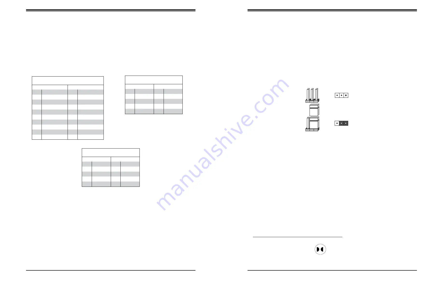
Type A USB 10 (3.0)
Pin Definitions
Pin#
Definition
Pin#
Definition
1
VBUS
5
SSRX-
2
USB_N
6
SSRX+
3
USB_P
7
GND
4
Ground
8
SSTX-
9
SSTX+
Front Panel USB (3.0/2.0)
Pin Definitions
Pin#
Definition
Pin#
Definition
1
VBUS
11
In
2
IntA_P1_SSRX-
12
IntA_P2_D-
3
IntA_
13
GND
4
GND
14
IntA_
5
IntA_P1_SSTX-
15
IntA_P2_SSTX-
6
IntA_
16
GND
7
GND
17
IntA_
8
IntA_P1_D-
18
IntA_P2_SSRX-
9
In
19
VBus
10
ID
Front Panel USB 2.0 Header
Pin Definitions
Pin#
Definition
Pin#
Definition
1
+5V
2
+5V
3
USB_PN2
4
USB_PN3
5
USB_PP2
6
USB_PP3
7
Ground
8
Ground
9
Key
10
Ground
Universal Serial Bus (USB) Ports
There are two USB 2.0 ports (USB0/1) and two USB 3.0 ports (USB2/3) located on the I/O
back panel. The X11SSZ-QF also has three front access USB 2.0 headers (USB4/5, USB6/7,
and USB8/9) and one front access USB 3.0 header (USB10/11). USB12 header is a Type
A header. The onboard headers can be used to provide front side USB access with a cable
(not included).
VGA/DVI Port
A VGA port and a DVI port are located next to the LAN ports on the I/O back panel. Use
these connections for VGA and DVI displays. The VGA connector is on top and the DVI is
on the bottom.
DP (DisplayPort)
There are two DisplayPorts located on the rear I/O back panel. DisplayPort, developed by
the VESA consortium, delivers digital display at a fast refresh rate. It can connect to virtually
any display using a DisplayPort adaptor for devices such as VGA, DVI, or HDMI.
4.4 Jumpers
Explanation of Jumpers
To modify the operation of the motherboard, jumpers are used to choose between optional
settings. Jumpers create shorts between two pins to change the function associated with it.
Pin 1 is identified with a square solder pad on the printed circuit board. See the motherboard
layout page for jumper locations.
Note:
On a two-pin jumper, "Closed" means the jumper is on both pins and "Open" indicates
the jumper is either on only one pin or has been completely removed.
Connector
Pins
Jumper
Setting
3 2 1
3 2 1
CMOS Clear
JBT1 is used to clear CMOS, which will also clear any passwords. Instead of pins, this jumper
consists of contact pads to prevent accidentally clearing the contents of CMOS.
To Clear CMOS
1. First power down the system and unplug the power cord(s).
2. Remove the cover of the chassis to access the motherboard.
3. Remove the onboard battery from the motherboard.
4.
Short the CMOS pads with a metal object such as a small screwdriver for at least four
seconds.
5. Remove the screwdriver (or shorting device).
6. Replace the cover, reconnect the power cord(s) and power on the system.
Notes:
Clearing CMOS will also clear all passwords.
Do not use the PW_ON connector to clear CMOS.
JBT1 contact pads


