background image

1-1

Chapter 1

Introduction

1-1

Overview

The SC745 air shroud is a configurable air shroud for system mainboards to enable 
maximum efficient air flow through the system. It can be configured to fit different sized 
Intel

®

 Xeon

 DP 5500/5400/5100/5000 series system mainboards of the same general 

shape and size. The SC745 air shroud is optimized for use with Supermicro SC745 
series chassis designs and for Supermicro X8Dxx/X7Dxx series mainboards. See 

Chapter 3

 for configuration details.

1-2

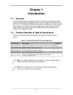
Product Checklist of Typical Components

The SC745 air shroud comes packaged with components and parts as shown in 

Table 1-1

:

Table 1-1. SC745 Air Shroud Parts and Components

Part Number

Description

Quantity

MCP-310-48001-0N

SC745 Intel DP plastic air shroud, supports up to 18 memory DIMM slots

MCP-310-48004-1N

SC745 X8 air shroud component part A 

1

MCP-310-48005-1N

SC745 X8 air shroud component part B

1

MCP-310-28005-1N

X8 air shroud universal component part C

1

MCP-310-28006-1N

X8 air shroud universal component part D, tear-drop Mylar 
module, 2.2” (55mm) wide

1

NOTE: 

The default configuration is for parts A, B, and C connected and with 

component part D in the accessory box separate.

NOTE: 

Each individual part for the SC745 air shroud is labeled with its 

component part letter for easy identification.

Summary of Contents for Supero SC745 Series

Page 1: ...SC745 Air Shroud User s Guide Revison 1 0 ...

Page 2: ...uper Micro s total liability for all claims will not exceed the price paid for the hardware product FCC Statement This equipment has been tested and found to comply with the limits for a Class A digital device pursuant to Part 15 of the FCC Rules These limits are designed to provide reasonable protection against harmful interference when the equipment is operated in a commercial environment This e...

Page 3: ...rofessionals only Manual Organization Chapter 1 Introduction The first chapter provides a checklist of the main components included with the SC745 air shroud and describes its main features Chapter 2 System Safety You should familiarize yourself with this chapter for a general overview of safety precautions that should be followed when installing and servicing the SC745 air shroud Chapter 3 Config...

Page 4: ...SC745 Air Shroud User s Guide iv Notes ...

Page 5: ...eral Safety Precautions 2 2 2 3 Electrostatic Discharge Precautions 2 2 2 4 Operating Precautions 2 2 Chapter 3 Configuration and Installation 3 1 3 1 Overview 3 1 3 2 SC745 Air Shroud Components 3 1 Component Part B 3 2 Component Part C 3 3 3 3 Removing Breakable Tabs for Cabling 3 5 3 4 Configuring the SC745 Air Shroud 3 6 Configuring for Configuration 1 3 7 Configuring for Configuration 2 3 8 C...

Page 6: ...SC745 Air Shroud User s Guide vi Notes ...

Page 7: ...hroud comes packaged with components and parts as shown in Table 1 1 Table 1 1 SC745 Air Shroud Parts and Components Part Number Description Quantity MCP 310 48001 0N SC745 Intel DP plastic air shroud supports up to 18 memory DIMM slots MCP 310 48004 1N SC745 X8 air shroud component part A 1 MCP 310 48005 1N SC745 X8 air shroud component part B 1 MCP 310 28005 1N X8 air shroud universal component ...

Page 8: ...tside of the shipping carton and mailed prepaid or hand carried Shipping and handling charges will be applied for all orders that must be mailed when service is complete For faster service RMA authorizations may be requested online at http www supermicro com support rma Whenever possible repack the chassis in the original Supermicro carton using the original packaging material If these are no long...

Page 9: ...uper Micro Computer B V Het Sterrenbeeld 28 5215 ML s Hertogenbosch The Netherlands Tel 31 0 73 6400390 Fax 31 0 73 6416525 Email sales supermicro nl General Information support supermicro nl Technical Support rma supermicro nl Customer Support Asia Pacific Address Super Micro Computer Inc 4F No 232 1 Liancheng Rd Chung Ho 235 Taipei County Taiwan R O C Tel 886 2 8226 3990 Fax 886 2 8226 3991 Web ...

Page 10: ...SC745 Air Shroud User s Guide 1 4 Notes ...

Page 11: ...making a complete circuit which will cause electrical shock Use extreme caution when using metal tools which can easily damage any electrical components or circuit boards they come into contact with Do not use mats designed to decrease electrostatic discharge as protection from electrical shock Instead use rubber mats that have been specifically designed as electrical insulators The power supply p...

Page 12: ...ts and printed circuit boards The following measures are generally sufficient to neutralize this difference before contact is made to protect your equipment from ESD Use a grounded wrist strap designed to prevent static discharge Keep all components and printed circuit boards PCBs in their antistatic bags until ready for use Touch a grounded metal object before removing the board from the antistat...

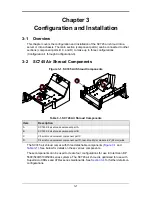
Page 13: ...e 3 1 and Table 3 1 See below for details on these various components These components can be used to create four configurations for use in Intel Xeon DP 5500 5400 5100 5000 series systems The SC745 air shroud is optimized for use with Supermicro X8Dxx and X7Dxx series mainboards See Section 3 4 for further details on configurations Figure 3 1 SC745 Air Shroud Components Table 3 1 SC745 Air Shroud...

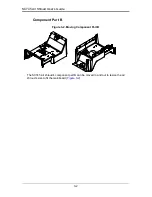
Page 14: ...Air Shroud User s Guide 3 2 Component Part B The SC745 air shroud s component part B can be moved in and out to resize the air shroud s size to fit the mainboard Figure 3 2 Figure 3 2 Moving Component Part B ...

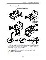
Page 15: ...n the inside of component part A It is attached and secured by placing locking tabs on its top into alignment slots provided on component part A Figure 3 3 Component Part C NOTE The view in Figure 3 3 has been modified in order to show the alignment slots more clearly Component Part C Locking Tabs Component Part A Alignment Slots ...

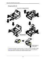
Page 16: ...ent part D 2 2 55mm wide tear drop Mylar module Figure 3 4 can be mounted on the underside of component part A by inserting its locking tabs into the component part A alignment slots provided Figure 3 4 Component Part D Component Part D Locking Tabs Component Part A Alignment Slots ...

Page 17: ...hat can be permanently removed to allow cabling access if required for your system Also component part C has breakable tabs that perform the same function See Figure 3 5 for details To remove simply cut or break the tabs or section off from its attachments with a pair of scissors and discard them Figure 3 5 Removing the Breakable Tabs Breakable Tabs ...

Page 18: ...se with Supermicro X8Dxx X7Dxx series mainboards Configuration 2 Component parts A B C and D for Intel Xeon DP 5500 5400 5100 5000 series systems with 12 x 13 form factor mainboards 7 PCI slots and 12 8 4 memory DIMM slots optimized for use with Supermicro X8Dxx X7Dxx series mainboards Configuration 3 Components parts A B and D for Intel Xeon DP 5500 5400 5100 5000 series systems with 13 68 x 13 f...

Page 19: ... 12 memory DIMM slots and a 12 x 13 form factor use Configuration 1 This configuration attaches component part B flush with the edge of component part A and mounts component parts C and D to the underside of component part A see Figure 3 6 This configuration is optimized for Supermicro X8Dxx X7Dxx series mainboards Figure 3 6 Configuration 1 Default Component Part C Component Part D Component Part...

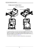
Page 20: ...mory DIMM slots and a 12 x 13 form factor use Configuration 2 This configuration attaches component part B one slot deeper than the edge of component part A and mounts component parts C and D to the underside of component part A see Figure 3 7 This configuration is optimized for Supermicro X8Dxx X7Dxx series mainboards Figure 3 7 Configuration 2 Component Part C Component Part D Component Part B ...

Page 21: ...M slots form factor use Configuration 3 This configuration attaches component part B one slot deeper than the edge of component part A and mounts component part D to the underside of component part A see Figure 3 8 This configuration is optimized for Supermicro X8Dxx X7Dxx series mainboards Figure 3 8 Configuration 3 NOTE Component part C is detached from this configuration Component Part D Compon...

Page 22: ... configuring the air shroud 2 Secure the rear edge of the SC745 air shroud to the top rear part of the chassis interior so that the SC745 mounting screw holes are aligned in with the mounting screw holes of the chassis and align so that the slot of air shroud s front mounts with the mounting tab at the top front part of the chassis interior see Figure 3 9 Figure 3 9 Inserting Air Shroud onto a Sys...

Page 23: ...n the mainboard of its system so that the air shroud covers the system mainboard over the CPU s and memory slots 4 Secure the top cover back on your system NOTE The air shroud should be mounted flush with the power supply housing if installing properly Some cable is supposed to go under the air shroud ...

Page 24: ...SC745 Air Shroud User s Guide 3 12 Notes ...

Page 25: ...cted to result in significant injury or loss of life or catastrophic property damage Accordingly Supermicro disclaims any and all liability and should buyer use or sell such products for use in such ultra hazardous applications it does so entirely at its own risk Furthermore buyer agrees to fully indemnify defend and hold Supermicro harmless for and against any and all claims demands actions litig...

Page 26: ...SC825 Air Shroud User s Guide Notes ...

Reviews: