C-6
SC842 Chassis Manual
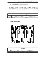
C-7 Front Jumper Locations and Pin Definitions
Explanation of Jumpers
To modify the operation of the backplane,
jumpers can be used to choose between
optional settings. Jumpers create shorts
between two pins to change the function
of the connector. Pin 1 is identified with
a square solder pad on the printed circuit
board. Note: On two pin jumpers, "Closed"
means the jumper is on and "Open" means
the jumper is off the pins.
Connector
Pins
Jumper
Setting
3 2 1
3 2 1
Jumper Settings
Jumper
Jumper Settings
Note
JP25
Open: 45 degrees Celcius
Pins 1-2: 50 degrees Celcius
Pins 2-3: 55 degrees Celcius
OH TEMP:
Overheat temperature settings
JP29
Pins 1-2: Reset
Pins 2-3: No reset
MG9072 chip reset
JP30
---
For manufacturer's use only
JP53
---
For manufacturer's use only
JP54
---
For manufacturer's use only
F1
F2
F3
JP52
1
2
7
8
JP51
1
2
7
8
J8
7
J7
7
J6
7
J5
7
J10
7
JP46
JP53
JP30
JP54
JP29
1
3
JP33
1
3
JP25
1
3
MH1
MH2
MH3
MH4
MH5
MH6
+
C45
+
C44
+
C3
+
C85
+
C5
+
C34
C35
U31
U26
U25
C
A
D3
4
1
JP10
4
1
JP13
1
16
32
33
48
49
64
U40
JP44
JP45
BAR CODE
1.01
REV:
SAS842TQ
MACH FINISH
30
ANGLE
SPECIFIED DIMENSIONS
UNLESS OTHERWISE
XXX
XX
X
.010
.03
.1
TOLERANCES
DECIMAL
ARE IN INCHES
Erni
DESINGER:
DATE: 08/11/2010
PROJECT NAME:
SAN JOSE,CA 95131
DESIGNED BY SUPERMICRO U.S.A.
www.supermicro.com
TEL:408-503-8000 FAX:408-503-8008
SILKSCREEN
PRIMARY-SIDE
S
UPER
R
S
UPER
S
UPER
S
UPER
S
UPER
S
UPER
S
UPER
S
UPER
S
UPER
S
UPER
S
UPER
S
UPER
S
UPER
S
UPER
S
UPER
S
UPER
S
UPER
S
UPER
RRRRRRRRRR
LED TEST
#4
#3
#2
#1
2-3:I2C
1-2:SGPIO
JP33:MODE
2-3: NO RST
1-2: RST
JP29:9072 RST
DESIGNED IN USA
SAS842T
Q
RE
V 1.01
#0
+5V
GND
GND
+12V
+5V
GND
+12V
GND
C
C
C
2-3:55
1-2:50
OPEN:45
JP25:OH TEMP.
D3:OH/DRIVE FAIL
UPGR
ADE
SIDEBAND#2
I2C#2
I2C#1
SIDEBAND#1
JP25
JP54
JP29
JP33
JP53
JP30
Figure C-2. Front Jumpers

