B-4
SC216 JBOD Chassis Manaual
Backplane
Main Power
4-Pin Connector
Pin# Definition
1
+12V
2 and 3
Ground
4
+5V
8. Backplane Main Power Connectors
The 4-pin connectors are designated
PWR1 - PWR6. They provide power to the
backplane. See the table on the right for
pin definitions.
B-5 Connector and Pin Definitions
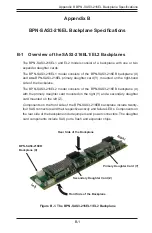
1. Flash Chips
The flash chip enhances the backplane memory.
2. Expander Chips
This expander chip allows the backplane to support dual ports, cascading, and
failover.
3. UART Connector
The UART connector is designated UART and J5. It is used for manufacturer's
diagnostic purposes only.
4. SDB Connector
The SDB connector is designated SDB and J10. It is the debug connector and
is used for manufacturer's diagnostic purposes only.
5. Internal Mini-SAS HD Connector
These connectors are cabled to the external Mini-SAS HD internal to external
adapter installed in the chassis rear.
6. Expander Connector
The primary expander connector designated PRI_i2C is reserved for future
expansion.
7. I
2
C Connector
In a JBOD configuration, the SMBus connector (J38) connects to the JBOD
control board, CSE-PTJBOD-CB3, to transmit management data between the
the backplane and the control board.

