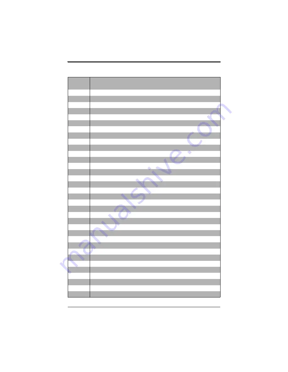
Supermicro SBA-7141M-T User Manual Download Page 59

A-5

:

22h 

1-3-1-3 Test 8742 Keyboard Controller

28h Auto 

size 

DRAM

29h 

Initialize POST Memory Manager

2Ah 

Clear 512 kB base RAM

2Ch

1-3-4-1 RAM failure on address line 

xxxx

*

2Eh

1-3-4-3 RAM failure on data bits 

xxxx

* of low byte of memory bus

2Fh 

Enable cache before system BIOS shadow

32h 

Test CPU bus-clock frequency

33h 

Initialize Phoenix Dispatch Manager

36h 

Warm start shut down

38h 

Shadow system BIOS ROM

3Ah Auto 

size 

cache

3Ch

Advanced configuration of chipset registers

3Dh

Load alternate registers with CMOS values

41h 

Initialize extended memory for RomPilot

42h Initialize 

interrupt 

vectors

45h 

POST device initialization

46h 

2-1-2-3 Check ROM copyright notice

47h 

Initialize I20 support

48h 

Check video configuration against CMOS

49h 

Initialize PCI bus and devices

4Ah 

Initialize all video adapters in system

4Bh 

QuietBoot start (optional)

4Ch 

Shadow video BIOS ROM

4Eh 

Display BIOS copyright notice

4Fh Initialize 

MultiBoot

50h 

Display CPU type and speed

51h 

Initialize EISA board

52h 

Test keyboard

54h 

Set key click if enabled

55h 

Enable USB devices

58h 

2-2-3-1 Test for unexpected interrupts

59h 

Initialize POST display service

5Ah 

Display prompt “Press F2 to enter SETUP”

5Bh 

Disable CPU cache

Table A-2. Terminal POST Errors  (Continued)

Post Code Description

Summary of Contents for SBA-7141M-T

Page 1: ...SBA 7141M T Blade Module User s Manual Revison 1 0b...

Page 2: ...es Super Micro s total liability for all claims will not exceed the price paid for the hardware product FCC Statement This equipment has been tested and found to comply with the limits for a Class A d...

Page 3: ...ety precautions that should be followed when installing and servicing the SBA 7141M T Blade Module Chapter 3 Setup and Installation Refer to this chapter for details on installing the SBA 7141M T Blad...

Page 4: ...SBA 7141M T Blade Module User s Manual iv Notes...

Page 5: ...llation 3 1 3 1 Overview 3 1 3 2 Installing Blade Modules 3 1 Powering Up a Blade Unit 3 1 Powering Down a Blade Unit 3 1 Removing a Blade Unit from the Enclosure 3 1 Removing Replacing the Blade Cove...

Page 6: ...ow To Change the Configuration Data 5 1 Starting the Setup Utility 5 1 5 2 BIOS Updates 5 2 Flashing BIOS 5 2 5 3 Running Setup 5 3 5 4 Main BIOS Setup Menu 5 4 System Time System Date 5 4 5 5 Advance...

Page 7: ...vii 5 7 Security Menu 5 14 5 8 Exit Menu 5 15 Appendix A BIOS POST Codes A 1 A 1 BIOS POST Messages A 1 A 2 BIOS POST Codes A 3 Recoverable POST Errors A 4 Terminal POST Errors A 4...

Page 8: ...SBA 7141M T Blade Module User s Manual viii Notes...

Page 9: ...Processor in a Socket 3 5 Figure 3 4 Installing the Onboard Battery 3 6 Figure 3 5 16 slot DIMM Numbering 3 8 Figure 3 6 Installing a DIMM into a Memory Slot 3 9 Figure 4 1 SBA 7141M T Blade Unit Fro...

Page 10: ...SBA 7141M T Blade Module User s Manual x Notes...

Page 11: ...ATA Configuration Submenu 5 7 Table 5 4 PCI PnP Configuration Submenu 5 8 Table 5 5 Super IO Configuration Submenu 5 9 Table 5 6 Chipset Configuration Submenu 5 9 Table 5 7 NorthBridge Configuration S...

Page 12: ...SBA 7141M T Blade Module User s Manual xii Notes...

Page 13: ...ng systems that have been certified for use with the SuperBlade www supermicro com products superblade 1 2 Product Checklist of Typical Components Your blade module ships with its mainboard already in...

Page 14: ...ts Populating two adjacent slots at a time with memory modules of the same size and type will result in interleaved 128 bit memory which is faster than non interleaved 64 bit memory Please refer to th...

Page 15: ...blade enclosure Each blade enclosure is a 7U form factor so a standard 42U rack may accommodate up to six enclosures with 60 blade modules or the equivalent of 60 1U servers With the inclusion of six...

Page 16: ...dress Super Micro Computer B V Het Sterrenbeeld 28 5215 ML s Hertogenbosch The Netherlands Tel 31 0 73 6400390 Fax 31 0 73 6416525 Email sales supermicro nl General Information support supermicro nl T...

Page 17: ...electrical shock Use extreme caution when using metal tools which can easily damage any electrical components or circuit boards they come into contact with Do not use mats designed to decrease electro...

Page 18: ...ponents and printed circuit boards The following measures are generally sufficient to neutralize this difference before contact is made to protect your equipment from ESD Use a grounded wrist strap de...

Page 19: ...sed management utility to apply power using either a CMM module or by the use of an installed SIMBL add on card in the blade module Powering Down a Blade Unit A blade unit may be powered down in eithe...

Page 20: ...the blade unit 3 To replace the cover fit the six grooves in the cover into the studs in the sides of the blade then slide the cover toward the front of the blade to lock it into place Installing a Bl...

Page 21: ...3 3 Chapter 3 Setup and Installation Figure 3 1 Inserting a Blade into the Enclosure Figure 3 2 Locking the Blade into Position...

Page 22: ...ocessor socket up until the processor is released from the socket then lift the silver cover plate and remove the processor Installing a Processor 1 If present remove the protective black PnP cap from...

Page 23: ...battery is included on the mainboard to supply certain volatile memory components with power when power has been removed from the blade module If this battery dies it must be replaced with an equival...

Page 24: ...banks with a CPU installed than to fill up one CPU memory bank while leaving another empty For example if you were to install eight DIMMs in a quad CPU configuration you should install two in the CPU...

Page 25: ...ng 16 Memory Slots and 4 CPUs for Interleaved Operation Number of DIMMS CPU0 CPU1 CPU2 CPU3 Channel 0 Channel 1 Channel 0 Channel 1 Channel 0 Channel 1 Channel 0 Channel 1 1A 1B 2A 2B 1A 1B 2A 2B 1A 1...

Page 26: ...lots 4 Insert each DIMM vertically into its slot paying attention to the notch along the bottom of the module to prevent inserting the module incorrectly see Figure 3 6 WARNING Exercise extreme care w...

Page 27: ...on the blade s mainboard 3 7 Installing the Operating System An operating system OS must be installed on each blade module Blades with Microsoft Windows OS and blades with Linux OS can both occupy and...

Page 28: ...ives installed and no bootable devices attached to it Once these conditions are met make sure the PXE server is running Then turn on the blade on which you wish to boot and or install the OS The BIOS...

Page 29: ...ade CD ROM for further details on the various functions provided by these management programs 3 9 Configuring and Setting up RAID The SBA 7141M T blade module accommodates only one hard drive therefor...

Page 30: ...SBA 7141M T Blade Module User s Manual 3 12 Notes...

Page 31: ...e Unit Features Feature Description Processors Supports four AMD Opteron 8300 8200 series processors Memory Supports up to 128 GB of ECC Registered DDR2 800 667 533 DIMMs in four 8 DIMM slot banks Sto...

Page 32: ...s blade module on and off 2 KVM Button N A Initiates KVM function 3 Power LED Green Indicates power status On Orange Indicates power status Off with power cables plugged in 4 KVM UID LED Blue Indicate...

Page 33: ...other blade disconnect the cable then reconnect it to the new blade See the Web based Management Utility User s Manual on your SuperBlade system CD ROM for further details on using the KVM function re...

Page 34: ...nit is a proprietary design which is based on the Nvidia MCP55 Pro chipset See Figure 4 4 for a block diagram of this chipset Figure 4 3 for a view of the BHQME mainboard and Figure 4 5 for an explode...

Page 35: ...ckets 2 DIMM Slots 3 Space for 2 5 SATA Hard Drive 4 SATA Connector 5 InfiniBand Connectors for InfiniBand cards 6 Gbx Connectors for power and logic to backplane 7 Nvidia MCP55 Pro chip 8 Onboard Bat...

Page 36: ...wn the blade and remove it from the enclosure 2 Remove the blade cover to access the mainboard see Section Removing Replacing the Blade Cover on page 3 2 for further details Short the CMOS pads with a...

Page 37: ...than non interleaved 64 bit memory See Section 3 5 for further details on mainboard memory installation Hard Disk Drives The SBA 7141M T blade unit can accommodate one internal 2 5 SATA hard disk dri...

Page 38: ...SBA 7141M T Blade Module User s Manual 4 8 Notes...

Page 39: ...he CMOS information that determines the system parameters may be changed by entering the BIOS Setup utility This Setup utility can be accessed by pressing the DELETE key at the appropriate time during...

Page 40: ...loppy disk Flashing a BIOS using the KVM Dongle 1 Copy the contents of the zip file to a bootable USB pen drive 2 Connect the KVM dongle CBL 0218L to the KVM connector at the front of the blade you wi...

Page 41: ...S120 PEPPCMM VIRTUAL DISC 1 to the top of the boot priority list 8 Exit while saving the changes The blade module will boot to the virtual media floppy image A 9 Type flash filename rom 5 3 Running Se...

Page 42: ...nu The BIOS setup utility uses a key based navigation system called hot keys Most of these hot keys F1 F10 ENTER ESC ARROW keys and so on can be used at any time during the setup navigation process Pr...

Page 43: ...time needed for the system to boot up The options are Enabled and DISABLED Quiet Boot If Disabled normal POST messages will be displayed on boot up If ENABLED this display the OEM logo instead of POS...

Page 44: ...this setting to either Enable or DISABLE the MCP55 ACPI HPET table X Power Configuration Power Button Mode Allows the user to change the function of the power button Options are On Off and SUSPEND Res...

Page 45: ...essor assisted virtualization Power Now This setting is used to ENABLE or Disable the AMD Power Now feature Thermal Throttling This setting is used to ENABLE or Disable Thermal Throttling Power Now Th...

Page 46: ...Set this value to allow or restrict the system from giving the VGA adapter card an interrupt address The options are Yes and NO Palette Snooping Select ENABLED to inform the PCI devices that an ISA gr...

Page 47: ...s I O port address and IRQ 4 for the interrupt address Serial Port2 Address This option specifies the base I O port address and Interrupt Request address of serial port 2 The options are DISABLED 2F8...

Page 48: ...tions are Auto Ganged Mode and ALWAYS unganged mode X ECC Configuration ECC Mode DRAM ECC allows hardware to report and correct memory errors automatically Options are Enabled and DISABLED 4 Bit ECC M...

Page 49: ...r Legacy USB Support Select Enabled to enable the support for USB Legacy Disable Legacy support if there are no USB devices installed in the system AUTO disables Legacy support if no USB devices are c...

Page 50: ...Event Log Configuration Submenu Menu Option Description View Event Log Highlight this item and press ENTER to view the contents of the event log Mark All Events as Read Highlight this item and press E...

Page 51: ...N 1 19200 8 N 1 AND 09600 8 N 1 Flow Control Selects the flow control to be used for console redirection Options are None HARDWARE and SOFTWARE Redirection After BIOS POST Options are DISABLE no redir...

Page 52: ...ser to specify the Boot sequence from the available drives 1st Drive Specifies the boot sequence for the 1st Removable Drive The options are USB PeppCMM Virtual Disc 1 and DISABLED 2nd Drive Specifies...

Page 53: ...is option to quit BIOS Setup without making any permanent changes to the system configuration and reboot the computer Select DISCARD CHANGES AND EXIT from the EXIT menu and press ENTER Discard Changes...

Page 54: ...SBA 7141M T Blade Module User s Manual 5 16 Notes...

Page 55: ...4k block at which the error was detected System RAM Failed at offset nnnn System RAM failed at offset nnnn of in the 64k block at which the error was detected Extended RAM Failed at offset nnnn Extend...

Page 56: ...n older boards check the cache jumpers You may have to replace the cache See your dealer A disabled cache slows system performance considerably CPU ID CPU socket number for Multi Processor error EISA...

Page 57: ...cking errors in binary data A parity error indicates that some data has been corrupted Parity Check 2 nnnn Parity error found in the I O bus BIOS attempts to locate the address and display it on the s...

Page 58: ...POST Errors Post Code Description 02h Verify Real Mode 03h Disable Non Maskable Interrupt NMI 04h Get CPU type 06h Initialize system hardware 07h Disable shadow and execute code from the ROM 08h Initi...

Page 59: ...ize extended memory for RomPilot 42h Initialize interrupt vectors 45h POST device initialization 46h 2 1 2 3 Check ROM copyright notice 47h Initialize I20 support 48h Check video configuration against...

Page 60: ...lize Intelligent System Monitoring 7Eh Initialize coprocessor if present 80h Disable onboard Super I O ports and IRQs 81h Late POST device initialization 82h Detect and install external RS232 ports 83...

Page 61: ...pt AAh Scan for F2 key stroke ACh Enter SETUP AEh Clear Boot flag B0h Check for errors B1h Inform RomPilot about the end of POST B2h POST done prepare to boot operating system B4h 1 One short beep bef...

Page 62: ...ory for PCMCIA CEh Initialize digitizer and display message D2h Unknown interrupt Table A 3 Boot Block Flash ROM Terminal POST Errors Post Code Description E0h Initialize the chipset E1h Initialize th...

Page 63: ...in the lower 16 bits The BIOS also sends the bitmap to the port 80 LED display It first displays the checkpoint code followed by a delay the high order byte another delay and then the low order byte o...

Page 64: ...SBA 7141M T Blade Module User s Manual A 10 Notes...

Page 65: ...ted to result in significant injury or loss of life or catastrophic property damage Accordingly Supermicro disclaims any and all liability and should buyer use or sell such products for use in such ul...

Page 66: ...SBA 7141M T Blade Module User s Manual...

Reviews: