Supermicro FatTwin F627G2-F73+ User Manual Download Page 69

Chapter 5: Advanced Motherboard Setup

5-15

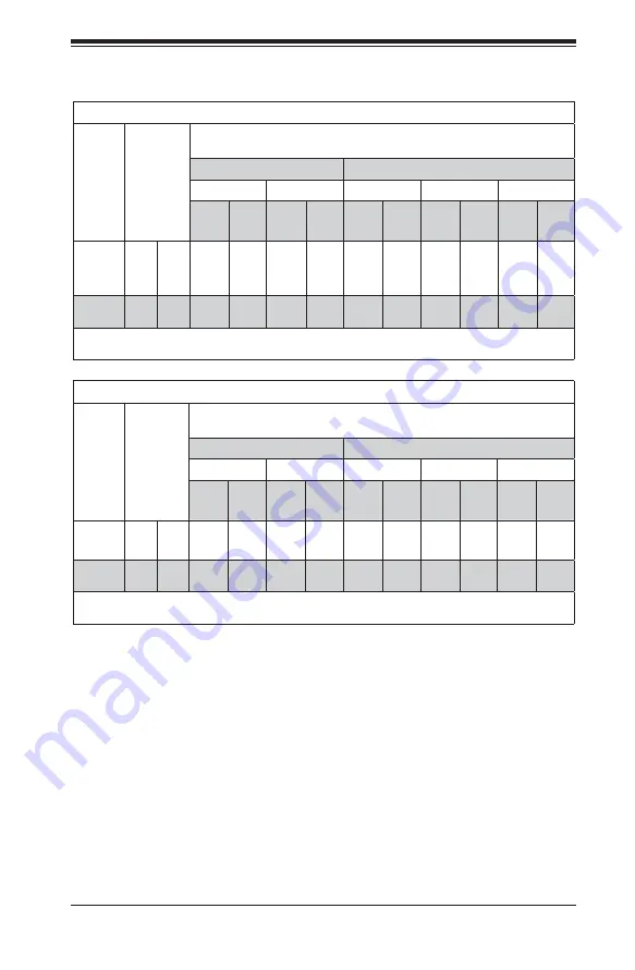
Populating LRDIMM (ECC) Memory Modules

Intel E5-2600(v2) Series Processor LRDIMM Memory Support

Ranks 

Per 

DIMM 

& Data 

Width

Memory 

Capacity 

Per DIMM

(in GB)

(See the 

Note 

Below)

Speed (MT/s) and Voltage Validated by Slot per Channel (SPC) and 

DIMM Per Channel (DPC)

2 Slots Per Channel

3 Slots Per Channel

1DPC

2DPC

1DPC

2DPC

3DPC

1.35V

1.5V

1.35V

1.5V

1.35V

1.5V

1.35V

1.5V

1.35V

1.5V

QRx4 

(DDP)

16

32

1066,
1333,

1600

1066,
1333,
1600,

1866

1066,
1333,

1600

1066,
1333,

1600

1066,
1333,

1600

1066,
1333,
1600,

1866

1066,
1333,

1600

1066,
1333,

1600

1066

1066

8Rx4 

(QDP)

32

64

1066

1066

1066

1066

1066

1066

1066

1066

1066

1066

Note: 

For detailed information on memory support and updates, please refer to the SMC Recommended 

Memory List posted on our website at 

http://www.supermicro.com/support/resources/mem.cfm.

Intel E5-2600 Series Processor LRDIMM Memory Support

Ranks 

Per 

DIMM 

& Data 

Width

Memory 

Capacity 

Per DIMM

(in GB)

(See the 

Note 

Below)

Speed (MT/s) and Voltage Validated by Slot per Channel (SPC) and 

DIMM Per Channel (DPC)

2 Slots Per Channel

3 Slots Per Channel

1DPC

2DPC

1DPC

2DPC

3DPC

1.35V

1.5V

1.35V

1.5V

1.35V

1.5V

1.35V

1.5V

1.35V

1.5V

QRx4 

(DDP)

16

32

1066

1066,

1333

1066

1066,

1333

1066

1066,

1333

1066

1066,

1333

1066

1066

QRx8 

(QDP)

8

16

1066

1066,

1333

1066

1066,

1333

1066

1066

1066

1066

1066

1066

Note: 

For detailed information on memory support and updates, please refer to the SMC Recommended 

Memory List posted on our website at 

http://www.supermicro.com/support/resources/mem.cfm.

Other Important Notes and Restrictions

• 

For the memory modules to work properly, please install DIMM modules of the 

same type, same speed and same operating frequency on the motherboard. 

Mixing of RDIMMs, UDIMMs or LRDIMMs is not allowed. Do not install both ECC 

and Non-ECC memory modules on the same motherboard.

• 

Using DDR3 DIMMs with different operating frequencies is not allowed. All 

channels in a system will run at the lowest common frequency.

Summary of Contents for FatTwin F627G2-F73+

Page 1: ...SUPER USER S MANUAL Revision 1 0b FatTwin F627G2 FT F627G2 FTPT F627G2 F73 F627G2 F73PT...

Page 2: ...n of any such disputes Super Micro s total liability for all claims will not exceed the price paid for the hardware product FCC Statement This equipment has been tested and found to comply with the li...

Page 3: ...n The first chapter provides a checklist of the main components included with the server system and describes the main features of the X9DRFF iG iTG 7G 7TG serverboards and the F424BG R1K62B chassis C...

Page 4: ...configuring the serverboard Chapter 6 Advanced Chassis Setup Refer to Chapter 6 for detailed information on the F424BG R1K62B server chassis You should follow the procedures given in this chapter when...

Page 5: ...v FatTwin F627G2 FT FTPT F73 F73PT USER S MANUAL Notes...

Page 6: ...wer Supply 1 4 Super I O 1 4 1 3 Server Chassis Features 1 5 System Power 1 5 SAS SATA Subsystem 1 5 I O Ports 1 5 Cooling System 1 5 Air Shrouds 1 5 Mounting Rails 1 6 1 4 Advanced Power Management 1...

Page 7: ...2 7 Checking the Drive Bay Setup 2 9 Chapter 3 System Interface 3 1 Overview 3 1 3 2 SCF424 Rear I O Control Panel 3 1 Control Panel Buttons 3 2 3 4 Drive Carrier LEDs 3 3 Chapter 4 Standardized Warn...

Page 8: ...of Jumpers 5 23 5 9 Onboard Indicators 5 25 5 10 Serial ATA Connections 5 27 5 11 Installing Drivers 5 28 SuperDoctor III 5 29 5 12 Serverboard Battery 5 31 Chapter 6 Advanced Chassis Setup 6 1 Static...

Page 9: ...6 20 Installing Rear 13 GPUs into the Node 6 20 Installing Rear 13 GPUs into a Node 6 22 6 13 Installing the Air Shroud 6 23 Air Shrouds 6 23 6 14 Checking the Airflow 6 24 Installation Complete 6 24...

Page 10: ...x Notes FatTwin F627G2 FT FTPT F73 F73PT USER S MANUAL...

Page 11: ...es BPN ADP F418L O P Four 4 backplanes for 2U GPU adapter cards BPN ADP 2UGPU O P SATA Backplane Four 4 backplanes each for six 6 2 5 HDD BPN SAS F424 B6 Four 4 40 cm and 45 cm 18AWG 8 pin male to two...

Page 12: ...8 GB of unbuffered ECC non ECC UDIMMs in DDR3 1600 1333 1066 800 MHz speed 1 GB 2 GB 4 GB 8 GB 16 GB or 32 GB size and at 1 35 or 1 5 voltages Please refer to Chapter 5 for installing memory Note For...

Page 13: ...controller and the term BMC controller can be used interchangeably in this section The Nuvoton WPCM450R Controller a Baseboard Management Controller BMC supports 2D VGA compatible Graphic Cores with P...

Page 14: ...ce RMII OS Operating System Independency Provides remote Hardware Health Monitoring via IPMI Key features Provides Network Management Security via remote access console redirection Supports the follow...

Page 15: ...more information visit our Web site at http www supermicro com I O Ports The F424BG is an proprietary form factor chassis designed to be used in a 4U rackmount configuration The F424BG chassis provide...

Page 16: ...rovides your system with real time thermal control and power management for maximum energy efficiency Although IPNM Specification Version 1 5 is supported by the BMC Baseboard Management Controller yo...

Page 17: ...8 0 7 Gen2 x4 VGA CONN LAN RJ45 RJ45 PHY RTL8201F LAN X540 SAS2308 AT25321 SATA2 1 DOM 6 3 1 5 3 1 5 3 1 5 3 1 5 3 1 5 6 3 1 5 I350 2 ports PCI Ex16x16 Proprietary SLOT PCI Ex16 Proprietary SLOT PCI E...

Page 18: ...ro com Europe Address Super Micro Computer B V Het Sterrenbeeld 28 5215 ML s Hertogenbosch The Netherlands Tel 31 0 73 6400390 Fax 31 0 73 6416525 Email sales supermicro nl General Information support...

Page 19: ...stop when a node is fully installed If too much force is used when inserting a node this pin may break off Take care to slowly slide a node in until you hear the click of the locking tab seating itse...

Page 20: ...1 10 FatTwin F627G2 FT FTPT F73 F73PT USER S MANUAL Notes...

Page 21: ...ged in any way If the server itself shows damage you should file a damage claim with the carrier who delivered it Decide on a suitable location for the rack unit that will hold the FatTwin F627G2 FT F...

Page 22: ...gle rack installation stabilizers should be attached to the rack In multiple rack installations the racks should be coupled together Always make sure the rack is stable before extending a component fr...

Page 23: ...i unit rack assembly the ambient operating temperature of the rack environment may be greater than the ambient temperature of the room Therefore consideration should be given to installing the equipme...

Page 24: ...m from a rack only Stability Hazard The rack stabilizing mechanism must be in place or the rack must be bolted to the floor before you slide the unit out for servicing Failure to stabilize the rack ca...

Page 25: ...ing Screw Outer Rail Locking Tab Locking Tabs Each inner rail has a locking tab This tab locks the chassis into place when installed and pushed fully into the rack These tabs also lock the chassis in...

Page 26: ...e front post of the rack Secure the front of the outer rail to the rack with two screws 3 Pull out the rear section of the outer rail adjusting the length until it fits within the posts of the rack 4...

Page 27: ...ssis Installation Installing the Chassis into a Rack 1 Confirm that the rails are correctly installed on the rack 2 Align the bottom of the chassis with the bottom of the rails 3 Insert the chassis in...

Page 28: ...place to allow proper airflow and prevent overheating Checking the Components and Setup 1 You may have one or two processors already installed into the serverboard Each processor needs its own heat si...

Page 29: ...ct airflow in and out of the server In addition if you are using a front bezel make sure the bezel s filter is replaced periodically 2 Do not operate the server without drives or drive trays in the dr...

Page 30: ...2 10 FatTwin F627G2 FT FTPT F73 F73PT USER S MANUAL Notes...

Page 31: ...ted on each of the motherboard nodes and on the drive carriers to keep you constantly informed of the overall status of the system This chapter explains the meanings of all LED indicators and the appr...

Page 32: ...ower supplied to the system Therefore you must unplug system before servicing The power button has a built in LED which will turn green when the power is on UID When used with a UID compatible motherb...

Page 33: ...carrier has a blue LED When illuminated this blue LED on the front of the SATA drive carrier indicates drive activity A connection to the SATA backplane enables this LED to blink on and off when that...

Page 34: ...FatTwin F627G2 FT FTPT F73 F73PT USER S MANUAL 3 4 Notes...

Page 35: ...nt for assistance Only certified technicians should attempt to install or configure components Read this appendix in its entirety before installing or configuring components in the Supermicro chassis...

Page 36: ...uipo considere los riesgos de la corriente el ctrica y familiar cese con los procedimientos est ndar de prevenci n de accidentes Al final de cada advertencia encontrar el n mero que le ayudar a encont...

Page 37: ...l kan veroorzaken Voordat u aan enige apparatuur gaat werken dient u zich bewust te zijn van de bij een elektrische installatie betrokken risico s en dient u op de hoogte te zijn van de standaard proc...

Page 38: ...schlie en des Systems an die Stromquelle die Installationsanweisungen lesen Advertencia Lea las instrucciones de instalaci n antes de conectar el sistema a la red de alimentaci n Attention Avant de br...

Page 39: ...erstromschutz installiert ist Stellen Sie sicher dass der Nennwert der Schutzvorrichtung nicht mehr als 250 V 20 A betr gt Advertencia Este equipo utiliza el sistema de protecci n contra cortocircuito...

Page 40: ...and the power cord removed from the power supply module s before accessing the chassis interior to install or remove system components 250V 20A Waarschuwing Dit product is afhankelijk van de kortsluit...

Page 41: ...tado de los m dulos de fuente de alimentaci n antes de tener acceso el interior del chasis para instalar o para quitar componentes de sistema Attention Le syst me doit tre d branch de toutes les sourc...

Page 42: ...nt Warnung Das Installieren Ersetzen oder Bedienen dieser Ausr stung sollte nur geschultem qualifiziertem Personal gestattet werden Advertencia Solamente el personal calificado debe instalar reemplaza...

Page 43: ...eug Schloss und Schl ssel oder einer sonstigen Sicherheitsvorkehrung m glich Advertencia Esta unidad ha sido dise ada para instalaci n en reas de acceso restringido S lo puede obtenerse acceso a una d...

Page 44: ...he same or equivalent type recommended by the manufacturer Dispose of used batteries according to the manufacturer s instructions Waarschuwing Dit apparaat is bedoeld voor installatie in gebieden met...

Page 45: ...ecommand e par le fabricant Jeter les piles usag es conform ment aux instructions du fabricant Advertencia Existe peligro de explosi n si la bater a se reemplaza de manera incorrecta Reemplazar la bat...

Page 46: ...zustellen dass der Einheit kein trom zugef hrt wird m ssen alle Verbindungen entfernt werden Advertencia Puede que esta unidad tenga m s de una conexi n para fuentes de alimentaci n Para cortar por co...

Page 47: ...System in Betrieb ist treten auf der R ckwandplatine gef hrliche Spannungen oder Energien auf Vorsicht bei der Wartung Advertencia Cuando el sistema est en funcionamiento el voltaje del plano trasero...

Page 48: ...ng Die Installation der Ger te muss den Sicherheitsstandards entsprechen Backplane Waarschuwing Een gevaarlijke spanning of energie is aanwezig op de backplane wanneer het systeem in gebruik is Voorzi...

Page 49: ...onal laws and regulations Advertencia La instalacion del equipo debe cumplir con las normas de electricidad locales y nacionales Attention L quipement doit tre install conform ment aux normes lectriqu...

Page 50: ...cyclage de ce produit sont g n ralement soumis des lois et ou directives de respect de l environnement Renseignez vous aupr s de l organisme comp tent Hot Swap Fan Warning Warning The fans might still...

Page 51: ...tfernt Advertencia Los ventiladores podran dar vuelta cuando usted quite ell montaje del ventilador del chasis Mandtenga los dedos los destornilladores y todos los objetos lejos de las aberturas del v...

Page 52: ...A UL CSA Supermicro UL CSA UL CSA Warnung Bei der Installation des Produkts die zur Verf gung gestellten oder benannt Anschlusskabel Stromkabel und Netzteile Verwendung anderer Kabel und Adapter kann...

Page 53: ...s dispositivos el ctricos que los productos designados por Supermicro solamente Attention Lors de l installation du produit utilisez les bables de connection fournis ou d sign L utilisation d autres c...

Page 54: ...en kabels stroomkabels en adapters Het gebruik van andere kabels en adapters kan leiden tot een storing of een brand Elektrisch apparaat en veiligheidsinformatiebladen wet verbiedt het gebruik van UL...

Page 55: ...bending keep one hand under the center of the board to support it when handling The following measures are generally sufficient to protect your equipment from electric static discharge Precautions Use...

Page 56: ...from the peripheral devices have been carefully routed in preconfigured systems to prevent them from blocking the flow of cooling air that moves through the system from front to back If you need to d...

Page 57: ...bit LAN 1 for F627G2 FTPT F627G2 F73PT 5 Gigabit LAN 2 for F627G2 FT F627G2 F73 or 10 Gigabit LAN 1 for F627G2 FTPT F627G2 F73PT 6 VGA Port 7 Power Switch LED Figure 5 1 Front I O Ports 2 1 5 3 4 6 7...

Page 58: ...ardware components Make sure that you install the processor into the CPU socket before you install the CPU heatsink Note Make sure to install the system board into the chassis before you install the C...

Page 59: ...1st WARNING WARNING Press down on Load the Lever labeled Close 1st Pull lever away from the socket Gently push down to pop the load plate open OPEN1st OPEN1st WARNING WARNING WARNING WARNING 4 Using y...

Page 60: ...the CPU on the socket Do not move the CPU horizontally or vertically Do not rub the CPU against the surface or against any pins of the socket to avoid damaging the CPU or the socket Caution You can on...

Page 61: ...cket Lock the lever labeled Close 1st first then lock the lever labeled Open 1st second Use your thumb to gently push the load levers down to the lever locks 9 Repeat steps to install a CPU to CPU Soc...

Page 62: ...f the old thermal grease Reapply the proper amount of thermal grease before you re install the heatsink Warning We do not recommend removing the CPU or the heatsink If you do need to remove the heatsi...

Page 63: ...lot until the module snaps into place 6 Press the release tabs to the locking positions to secure the DIMM module into the slot Reverse the steps above to remove the DIMM modules from the motherboard...

Page 64: ...e Number of CPUs DIMMs CPU and Memory Population Configuration Table For memory to work properly please follow the tables below 1 CPU 2 DIMMs CPU1 P1 DIMMA1 P1 DIMMB1 1 CPU 4 DIMMs CPU1 P1 DIMMA1 P1 D...

Page 65: ...N A 1066 1333 1600 DRx8 Non ECC 2GB 4GB 8GB NA 1066 1333 1600 1866 NA 1066 1333 1600 N A 1066 1333 1600 1866 N A 1066 1333 1600 SRx16 Non ECC 512 MB 1GB 2GB NA 1066 1333 1600 1866 NA 1066 1333 1600 N...

Page 66: ...Rx8 Non ECC 1GB 2GB 4GB NA 1066 1333 NA 1066 1333 N A 1066 1333 N A 1066 1333 DRx8 Non ECC 2GB 4GB 8GB NA 1066 1333 NA 1066 1333 N A 1066 1333 N A 1066 1333 SRx16 Non ECC 512 MB 1GB 2GB NA 1066 1333 N...

Page 67: ...1600 800 800 1066 DRx8 2 4 8 1066 1333 1066 1333 1600 1866 1066 1333 1066 1333 1600 1066 1333 1066 1333 1600 1866 1066 1333 1066 1333 1600 800 800 1066 SRx4 2 4 8 1066 1333 1066 1333 1600 1866 1066 13...

Page 68: ...1066 1333 1066 1333 1600 N A 800 1066 DRx8 2 4 8 1066 1333 1066 1333 1600 1066 1333 1066 1333 1600 1066 1333 1066 1333 1600 1066 1333 1066 1333 1600 N A 800 1066 SRx4 2 4 8 1066 1333 1066 1333 1600 1...

Page 69: ...ort Ranks Per DIMM Data Width Memory Capacity Per DIMM in GB See the Note Below Speed MT s and Voltage Validated by Slot per Channel SPC and DIMM Per Channel DPC 2 Slots Per Channel 3 Slots Per Channe...

Page 70: ...WD1 JPG1 JBR1 1 JP6 JP7 CPLD1 JBT1 HDD_ACT_LED1 JI2C2 JI2C1 JBAT1 CPU2 BIOS PCH SLOT4 PCIE E 2 0X4 CPU1 SLOT3 PCI E 3 0X8 CPU1 SLOT2 PCI E 3 0X8 CPU1 SLOT1 PCI E X16 PROPRIETARY SLOT P2 DIMMH2 P2 DIMM...

Page 71: ...ufacturer Do not install the onboard battery upside down to avoid possible explosion 3 Both the X9DRFF iTG and X9DRFF 7TG serverboards include 10 GB Ethernet ports 4 Jumpers not indicated are for test...

Page 72: ...4 pin External BMC I2 C Header for IPMI Card JPI2 C1 Power Supply SMBbus I2 C Header JPW1 JPW2 8 pin Power Connectors JPW3 4 pin Power Connector JSD1 SATA Device Power Connector JTPM1 TPM Trusted Pla...

Page 73: ...tions 12V 8 pin PWR JPW1 2 Pin Definitions Pins Definition 1 4 Ground 5 8 12V 12V 4 pin PWR JPW3 Pin Definitions Pins Definition 1 Ground 2 Ground 3 5V SB 4 PS_ON_N HDD PWR Pin Definitions Pins Defini...

Page 74: ...17 Ground 9 TD3 18 Ground NC indicates no connection Power Button Unit Identifier Switch A Unit Identifier switch SW1 and a UID LED Indicator are located on the serverboard In addition a power button...

Page 75: ...2 S SGPIO 1 2 Pin Definitions Pin Definition Pin Definition 1 NC 2 NC 3 Ground 4 Data 5 Load 6 Ground 7 Clock 8 NC NC indicates no connection Fan Headers This serverboard has eight 4 pin Fan1 Fan8 an...

Page 76: ...the UID switch the UID LED UID_LED1 will be turned on Push the UID switch again to turn off the LED indicator The UID switch provides easy identification of a system unit that may be in need of servi...

Page 77: ...is used to clear CMOS which will also clear any passwords Instead of pins this jumper consists of contact pads to prevent accidentally clearing the contents of CMOS To Clear CMOS 1 First power down th...

Page 78: ...e the table on the right for jumper settings BMC Enable Jumper JPB1 allows you to enable the embedded BMC Baseboard Management Controller to provide IPMI 2 0 support on the motherboard See the table o...

Page 79: ...the connection See the tables at right for more information LAN Connection Speed Indicator Left LED Settings LED Color Definition Off 10 MHz Green 100 MHz Amber 1 GHz Activity LED Link Speed LED GLAN...

Page 80: ...g HDD Active Off HDD Disabled or Failed SAS Heartbeat LED A SAS Heartbeat LED is located at SAS_HB_LED1 on the motherboard When LEDS2 is blinking SAS is working properly SAS Heartbeat LED SAS_HB_LED1...

Page 81: ...cated on the motherboard I SATA Ports 0 1 support SATA 3 0 I SATA Ports 2 5 and S SATA 0 support SATA 2 0 In addition eight SAS ports L SAS 0 7 supported by the LSI SAS 2208 Controller are also locate...

Page 82: ...directory and locate the ISO file for your motherboard Download this file to create a CD DVD of the drivers and utilities it contains You may also use a utility to extract the ISO file if preferred A...

Page 83: ...is called SD III Client The SuperDoctor III program allows you to monitor the environment and operations of your system SuperDoctor III displays crucial system information such as CPU temperature sys...

Page 84: ...and User s Manual can be downloaded from the Supermicro web site at http www supermicro com products accessories software SuperDoctorIII cfm For Linux we recommend that you use the SuperoDoctor II app...

Page 85: ...urer CR2032 Dispose of used batteries according to the manufacturer s instructions Figure 5 7 Installing the Onboard Battery LITHIUM BATTERY BATTERY HOLDER Please handle used batteries carefully Do no...

Page 86: ...5 32 FatTwin F627G2 FT FTPT F73 F73PT USER S MANUAL Notes...

Page 87: ...very carefully The following measures are generally sufficient to protect your equipment from ESD damage Precautions Use a grounded wrist strap designed to prevent static discharge Touch a grounded me...

Page 88: ...rol Panel The control panel for each node is located on the front of the chassis The LEDs inform you of system status See Chapter 3 for details on the LEDs and the control panel buttons Ethernet Ports...

Page 89: ...supply 3 If your system has dual redundant power supplies remove the cords from both power supplies 4 Disconnect the cord from the power strip or wall outlet 6 4 Removing Nodes from the Chassis Each...

Page 90: ...that node will power down as well Refer to the charts below and on the following pages for your specific chassis configuration These instructions apply to hot swappable hard drives in both 2 5 and 3...

Page 91: ...be removed without powering down the server The procedure to remove hard drives from the node is the same for both models Removing Hard Drive Carriers from the Chassis 1 Press the release button on t...

Page 92: ...ves are mounted in drive carriers to simplify their installation and removal from the chassis These carriers also help promote proper airflow through the drive bays Removing the Dummy Drive from the D...

Page 93: ...th the hard drive securing it from the bottom of the carrier 4 Use the open handle of the drive carrier to insert the drive carrier into the open drive bay 5 Secure the drive carrier into the drive ba...

Page 94: ...Node Configurations Node configuration specifications are shown in the table below F424BG R1K62B Front of Node Rear of Node Two low profile expansion PCIE slots Six 2 5 HDDs Two optional fixed fans Fi...

Page 95: ...over 1 Power down the system and remove the power cord from the rear of the power supply as described in Section 6 3 Remove the node from the chassis as described in Section 6 4 and place the node on...

Page 96: ...om the Node 1 Remove the power cord from the rear of the node as described in Section 6 2 Remove the node from the chassis as described in Section 6 3 Place the node on a flat stable surface and remov...

Page 97: ...of the node 3 Align the mounting holes in the backplane with the holes in the chassis Replace the screws securing the backplane to the Node Figure 6 10 Installing the Backplane F424BG R1K62B Install F...

Page 98: ...rear of the node as described in Section 6 3 Remove the node from the chassis as described in Section 6 4 Place the node on a flat stable surface and remove the node cover as described in Section 6 7...

Page 99: ...utor board with the two screws previously set aside Do not exceed eight pounds of torque when tightening the screws 9 Put the support bracket back into place in the node and secure it with the screw p...

Page 100: ...d it is also possible that some of the optional standoffs which are pre installed in the chassis may need to be removed Add or remove standoffs as needed Installing the Motherboard 1 Review the docume...

Page 101: ...s front panel and power supply as needed The fans may be temporarily removed to allow access to the backplane ports 8 Replace the expansion card bracket and secure the bracket with a screw 9 Repeat st...

Page 102: ...To install low profile expansion cards follow the instructions on the following pages Figure 6 16 PCIE Slot Shield Configuration PCIE Slot Cover F424BG PCIE Slot Configurations The F424BG chassis sup...

Page 103: ...described in Section 6 7 2 Remove the mounting screw which secures the PCI E slot cover in the PCI E slot and set this aside for later use 3 Remove the PCI E slot cover by sliding it upward and out o...

Page 104: ...o date list of compatible GPUs visit the Supermicro web site at www supermicro com Installing Front 10 5 GPUs into the GPU Bracket Installing a Front 10 AMD Whoodier GPU into a Bracket 1 Remove the po...

Page 105: ...bed in Section 6 7 2 Position the NVIDIA GPU as illustrated below 3 Insert the GPU into the GPU bracket and secure with four screws 4 Confirm that the GPU is securely mounted in the GPU bracket Instal...

Page 106: ...e GPU bracket to the node as shown using the four screws provided 4 Proceed to the next section to install the rear internal 13 GPUs Installing Rear 13 GPUs into the Node Installing a Rear 13 AMD Wood...

Page 107: ...in the previous section 2 Secure the three mounting brackets with three screw 3 Insert the GPU into the GPU bracket and secure with three screws 4 Confirm that the GPU is securely mounted in the GPU b...

Page 108: ...ction 2 Position the GPU bracket in the node as illustrated below 3 Secure the GPU bracket to the node as shown using the four screws provided 4 Attach the stabilizing bracket to the GPU bracket 5 Sec...

Page 109: ...e node from the chassis as described in Section 6 4 Place the node on a flat stable surface and remove the node cover as described in Section 6 7 2 Make sure that the motherboard and all components ar...

Page 110: ...a drive or dummy drive in the carrier Use only recommended server parts 3 Make sure no wires or foreign objects obstruct airflow through the chassis Pull all excess cabling out of the airflow path or...

Page 111: ...e without tools Removing a Rear Exhaust Fan 1 Determine which node contains the failed fan and power down the node with the operating system 2 Remove the power cord from the rear of the node as descri...

Page 112: ...s In the unlikely event that the power supply unit needs to be replaced one power supply can be removed without powering down the system Replacement units can be ordered directly from Supermicro See t...

Page 113: ...ame displays all the options that can be configured Grayed out options cannot be configured Options in blue can be configured by the user The right frame displays the key legend Above the key legend i...

Page 114: ...utility From the main menu you can access the other setup screens An AMI BIOS identification string is displayed at the left bottom corner of the screen below the copyright message Warning Do not upgr...

Page 115: ...format e g 15 32 52 Supermicro X9DRFF iG iTG 7G 7TG Version This item displays the SMC version of the BIOS ROM used in this system Build Date This item displays the date that the BIOS ROM was built Me...

Page 116: ...key is pressed if an error occurs The options are Disabled and Enabled Interrupt 19 Capture Interrupt 19 is the software interrupt that handles the boot disk function When this item is set to Enabled...

Page 117: ...ct Power On for the system power to be turned on after a power loss Select Last State to allow the system to resume its last state before a power loss The options are Power On Stay Off and Last State...

Page 118: ...t to Enabled to use the processor s second core and above Please refer to Intel s website for more information The options are All 1 2 4 and 6 Limit CPUID Maximum Use this feature to set the maximum C...

Page 119: ...led for DCU Data Cache Unit IP Prefetcher support which will prefetch IP addresses to improve network connectivity and system performance The options are Enabled and Disabled Intel Virtualization Tech...

Page 120: ...CPU C6 State ACPI C3 to the operating system During the CPU C6 State the power to all cache is turned off The options are Enabled and Disabled CPU C7 Report Available when Power Technology is set to...

Page 121: ...he time period during which short duration power in watts is maintained The default setting is 0 Chipset Configuration North Bridge This feature allows the user to configure the settings for the Intel...

Page 122: ...lable PCI Express lanes are distributed between the PCI Exp Root ports CPU 1 Slot J1 PCI E 3 0 x16 Link Speed Select GEN1 to enable PCI Exp Generation 1 support for Slot J1 Select GEN2 to enable PCI E...

Page 123: ...onfiguration Current QPI Link Speed This item displays the current speed of the QPI Link Current QPI Link Frequency This item displays the frequency of the QPI Link Isoc Select Enabled to enable Isoch...

Page 124: ...dentical copies of all data in memory for data backup When Lockstep is selected the motherboard uses two areas of memory to run the same set of operations in parallel The options are Independent Mirro...

Page 125: ...ed and sent to the requestor the original source Memory is updated as well Select Enabled to use Demand Scrubbing for ECC memory correction The options are Enabled and Disabled Data Scrambling Select...

Page 126: ...O port 60h 64h emulation support for the legacy USB keyboard so that it can be fully supported by the operating systems that does not recognize a USB device The options are Disabled and Enabled EHCI...

Page 127: ...ctive state when I O activity resumes The options are Enabled and Disabled Port 0 5 Hot Plug Select Enabled to enable hot plug support for a particular port which will allow the user to change a hardw...

Page 128: ...mum Payload Select Auto to allow the system BIOS to automatically set the maximum payload value for a PCI E device to enhance system performance The options are Auto 128 Bytes and 256 Bytes 512 Bytes...

Page 129: ...computer using a network device Select PXE Preboot Execution Environment to use an PXE Option ROM to boot the computer using a network device The options are PXE iSCSI and FCoE Load Onboard LAN1 Optio...

Page 130: ...nicate with the client computer which is the remote computer used by the user Terminal Type This feature allows the user to select the target terminal emulation type for Console Redirection Select VT1...

Page 131: ...edirection to prevent data loss caused by buffer overflow Send a Stop signal to stop sending data when the receiving buffer is full Send a Start signal to start sending data when the receiving buffer...

Page 132: ...user to specify how the host computer will exchange data with the client computer which is the remote computer used by the user Out of Band Management Port The feature selects a serial port used by th...

Page 133: ...uctions In this setting power to the CPU s and RAM is maintained but RAM is refreshed Select Suspend Disabled to use power reduced mode Power will only be supplied to limited components such as RAMs t...

Page 134: ...his item to schedule an operation for the security device The options are None Enable Take Ownership Disable Take Ownership and TPM Clear Note Upon system reset the computer will reboot in order to ex...

Page 135: ...anagement BIOS event logging during system boot The options are Enabled and Disabled Runtime Error Logging Support Select Enabled to support runtime error logging The options are Enabled and Disabled...

Page 136: ...ng when the SMBIOS event log is full The options are Do Nothing and Erase Immediately SMBIOS Event Log Standard Settings Log System Boot Event Select Enabled to log system boot events The options are...

Page 137: ...in your system System Event Log Enabling Disabling Options SEL Components Select Enabled for all system event logging at bootup The options are Enabled and Disabled Erasing Settings Erase SEL Select...

Page 138: ...and Yes Configuration Address Source Use this feature to select the source of the IP address for this computer If Static is selected you will need to know the IP address of this computer and enter it...

Page 139: ...ot Priority 1st Boot Device 2nd Boot Device 3rd Boot Device etc Use these items to specify the sequence of boot device priority Delete Boot Option Use this feature to select a boot device to delete fr...

Page 140: ...rmines when a password entry is required If Setup is selected the user is required to enter a password upon entering the BIOS setup utility If Always is selected the user is required to enter a passwo...

Page 141: ...and Reset When you have completed the system configuration changes select this option to save the changes and reboot the computer so that the new system configuration settings can take effect Select...

Page 142: ...tings as the user s defaults When the dialog box appears asking you if you want to save values as user s defaults click Yes to save the current values as user s default settings or click No to keep th...

Page 143: ...GB of unbuffered ECC non ECC UDIMMs at DDR3 1600 1333 1066 800 MHz speed and 1 GB 2 GB 4 GB 8 GB 16 GB or 32 GB size Note refer to Chapter 5 for details and to our web site for updates to supported me...

Page 144: ...m Input Requirements AC Input 1000W Output 100 120V 12 10A 50 60Hz 1200W Output 120 140V 12 10A 50 60Hz 1620W Output 180 240V 10 5 8A 50 60Hz Efficiency 80 Platinum Level Power Supply Rated Output Pow...

Page 145: ...ic Emissions FCC Class A EN 55022 Class A EN 61000 3 2 3 3 CISPR 22 Class A Electromagnetic Immunity EN 55024 CISPR 24 EN 61000 4 2 EN 61000 4 3 EN 61000 4 4 EN 61000 4 5 EN 61000 4 6 EN 61000 4 8 EN...

Page 146: ...to perform be reasonably expected to result in significant injury or loss of life or catastrophic property damage Accordingly Supermicro disclaims any and all liability and should buyer use or sell su...

Reviews: