


Chapter 5: Advanced Serverboard Setup
5-13
5-12
S
UPER
S
TORAGE
S
YSTEM 6048R-E1CR60N/L User's Manual
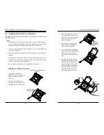
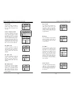
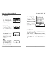
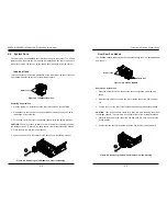
Reset Button
The Reset Button connection is
located on pins 3 and 4 of JF1 and
attaches to the reset switch on the
computer chassis. See the table on
the right for pin definitions.
Power Button
The Power On connection is on pins
1 and 2 of JF1. These should be con-
nected to the chassis power button.
Momentarily contacting both pins will
power on/off the system. To turn off
the power when the system is on,
press the button for 4 seconds or
longer. See the table on the right for
pin definitions.
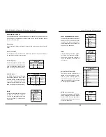
5-7 Connector Definitions
ATX Power 24-pin Connector
Pin Definitions
Pin# Definition Pin # Definition
13
+3.3V
1
+3.3V
14
-12V
2
+3.3V
15
COM
3
COM
16
PS_ON
4
+5V
17
COM
5
COM
18
COM
6
+5V
19
COM
7
COM
20
Res (NC)
8
PWR_OK
21
+5V
9
5VSB
22
+5V
10
+12V
23
+5V
11
+12V
24
COM
12
+3.3V
Reset Button
Pin Definitions (JF1)
Pin# Definition
3
Reset
4
Ground
Power Button
Pin Definitions (JF1)
Pin# Definition
1
Power Signal
2
Ground
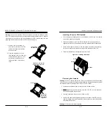
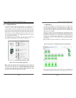
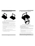
Secondary Power Connector
JPW2 and JPW3 must also be con-
nected to the power supply. See the
table on the right for pin definitions.
Required Connection
+12V 8-pin Power
Pin Definitions
Pins Definition
1 - 4
Ground
5 - 8
+12V
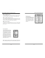
Warning
: To provide adequate power supply to the serverboard, be sure to connect
JPW1 and both JPW2 and JPW3 to the power supply. Failure to do so will void the
manufacturer warranty on your power supply and serverboard.
Power Connectors
A 24-pin main power supply connec-
tor (JPW1) and two 8-pin CPU power
connectors (JPW2/JPW3) must be
connected to the power supply to pro-
vide adequate power to the system.
These power connectors meet the SSI
EPS 12V specification. See the table
on the right for pin definitions.
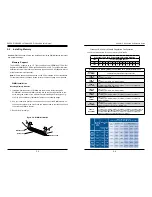
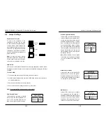
Quick Reference (cont.)
LED
Description
State Status
LED_A1-A3 CPU1 Memory Fail LED for DIMMs A1-A3
On
Memory Failure
LED_B1-B3 CPU1 Memory Fail LED for DIMMs B1-B3
On
Memory Failure
LED_C1-C3 CPU1 Memory Fail LED for DIMMs C1-C3
On
Memory Failure
LED_D1-D3 CPU1 Memory Fail LED for DIMMs D1-D3
On
Memory Failure
LED_E1-E3 CPU2 Memory Fail LED for DIMMs E1-E3
On
Memory Failure
LED_F1-F3
CPU2 Memory Fail LED for DIMMs F1-F3
On
Memory Failure
LED_G1-G3 CPU2 Memory Fail LED for DIMMs G1-G3 On
Memory Failure
LED_H1-H3 CPU2 Memory Fail LED for DIMMs H1-H3
On
Memory Failure
Summary of Contents for 6048R-E1CR60L
Page 1: ...SUPER STORAGE SYSTEM 6048R E1CR60N 6048R E1CR60L USER S MANUAL 1 0 ...
Page 6: ...Notes SUPERSTORAGESYSTEM 6048R E1CR60N L User s Manual x ...
Page 10: ...1 6 SUPERSTORAGESYSTEM 6048R E1CR60N L User s Manual Notes ...
Page 30: ...4 20 SUPERSTORAGESYSTEM 6048R E1CR60N L User s Manual Notes ...
Page 56: ...6 22 SUPERSTORAGESYSTEM 6048R E1CR60N L User s Manual Notes ...
Page 77: ...7 40 SUPERSTORAGESYSTEM 6048R E1CR60N L User s Manual Notes ...
Page 79: ...A 2 SUPERSTORAGESYSTEM 6048R E1CR60N L User s Manual Notes ...