


28
S
uperior
B
roadcast
P
roducts
Blue Digital Exciter
User Manual
24 / 44
User Manual
Rev. 1.0 - 20/11/09
DTVC
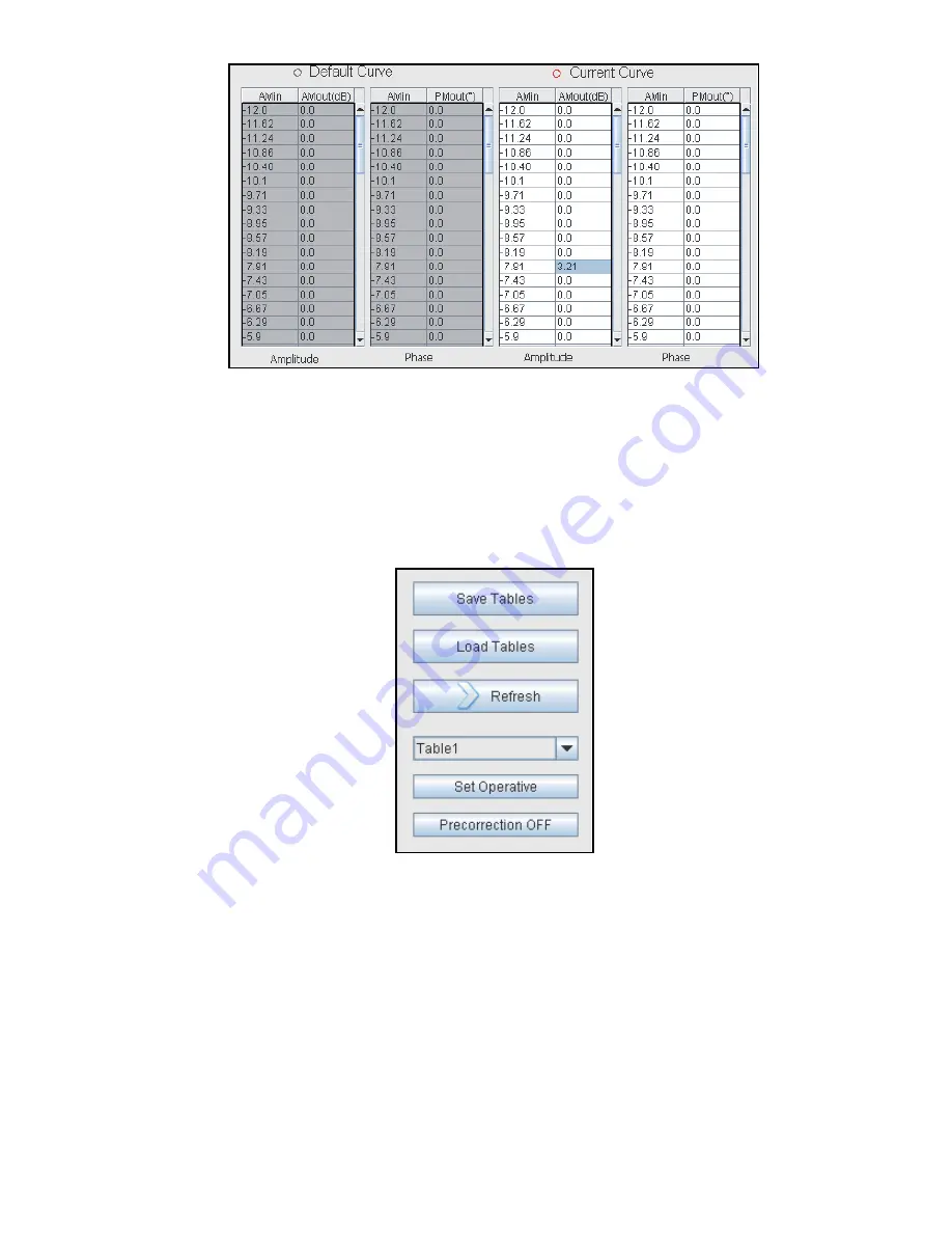
The
rst two tables are referred to the Default values, therefore cannot be
modi
ed, and are referred to the amplitude and to the phase. The last two
tables are the ones that are currently viewed in the present graphic and can
be modi
ed for what concerns amplitude and phase by the user. On the
rst
column of each table it is pointed out the
xed abscissa and on the second
column the ordinate which value can be modi
ed by the user.
The buttons allow to do the main operations:
◦
Save Tables: allows to save all the precorrection’s curves on different text’s
les located in the /TABLE directory.
◦
Load Tables: allows to load all the precorrection’s curves from different text’s
les located in the /TABLE directory.
◦
Refresh: allows to send the current curve (both amplitude and phase) to the
modulator, making effective in the spectrum the table’s changing.
◦
Table selector: allows to select what type of table is visualized (Table0(Default),
Table1, ..., Table6).
◦
Set Operative: allows to set the current curves (both amplitude and phase)
as the active curve in the modulator at every start up.


