GAS SOLDERING IRON
4
UNPACKING
1.
Unpack all the components from the packaging.
2.
When unpacking the S15005 Gas Soldering Iron, carefully inspect for any damage that may have occurred during transit.
3.
Check for loose, missing or damaged parts.
4.
Ensure all packaging materials are disposed of as per your local council guide lines.
1. REFILLING OPERATION
Note: Gas soldering Iron does NOT come filled with gas.
WARNING!:
Before each use and after refilling, listen for leaks. Never use a flame to check for leaks, always use
soapy water to identify leaks in gas.
1.
Ensure that the gas soldering iron is extinguished, in the OFF position and cool before refilling.
2.
Allow sufficient time for the S15005 to cool to room temperature before refilling the gas soldering iron with fuel.
3.
Refill S15005 in a well-ventilated area, free of fire or other sources of ignition, away from bystanders and any
flammable substance.
4.
Never smoke while refilling the S15005.
5.
Hold the S15005 with the FILL VALVE (8) facing upwards (located on the base of the S15005).
6.
Invert the refueling canister (not supplied), then insert the butane canister tip into the FILL VALVE (8). Adaptors may be
needed, depending on refueling canister type (not supplied).
7.
Push the butane canister and S15005 together and allow gas to flow into the INTERNAL GAS STORAGE TANK.
8.
The S15005 should take approximately 5 to10 seconds to fill.
9.
Stop refilling once the gas begins to expel from the FILL VALVE (8).
10. Wait approximately 2 minutes to allow the gas to stabilize before igniting the S15005.
2. Understanding The Gas Soldering Iron Components
1.
The IGNITER SWITCH/STAND (7) is used to operate the tool, or can be used as a tool rest allowing a hot soldering iron to
remain a safe distance away from your workspace (Fig 1).
2.
With the tool resting on the IGNITER/SWITCH STAND (7), the soldering iron can be placed onto a flat surface during operation
or once turned OFF, the soldering iron can cool down without making contact with your workspace.
3.
Always ensure the Protective Cap (11) is fitted to the soldering iron as described in 7. INSTALLING PROTECTIVE CAP page 5
when not in use (Fig 2).
3. LIGHTING AND OPERATION
WARNING!:
Before each use, ensure that LOCKING NUT (5) and related tip is securely connected and tight.
A. Press and Hold Mode
NOTE:
Turn TEMPERATURE ADJUSTMENT KNOB (9) approximately halfway between (2) and (3) position, located below
the underside of the Soldering Iron.
1.
Press the LOCK OFF BUTTON (6) down and slide the IGNITER SWITCH/STAND (7) away from burner tip, adjust the Soldering
Iron temperature as desired.
2.
To turn OFF the S15005, release IGNITER SWITCH/STAND (7) to extinguish S15005.
B. Continuous Mode
NOTE:
Turn TEMPERATURE ADJUSTMENT KNOB (9) approximately halfway between (2) and (3) position.
1.
Press the LOCK OFF BUTTON (6) button down and slide the IGNITER SWITCH/STAND (7) away from the BURNER.
2.
Slide CONTINUOUS LOCK (10) to “CONTINUOUS” position to lock the IGNITER SWITCH/STAND (7) in the ON position.
3.
Release IGNITER SWITCH/STAND (7) and the Soldering Iron will now be in Continuous Operation Mode, adjust the Soldering
Iron temperature as desired.
4.
To extinguish the S15005 slide the CONTINUOUS LOCK (10) to “OFF” position.
(Fig 1)
(Fig 2)
5
GAS SOLDERING IRON
4. ADJUST FLAME/TEMPERATURE
1.
Slide FLAME ADJUSTMENT KNOB (9) to “1” for small flame/low temperature (Fig 3).
2.
Slide FLAME ADJUSTMENT KNOB (9) to “4” for large flame/high temperature (Fig 4).
5. USING AS SOLDERING IRON
1.
The S15005 is setup for use as a soldering iron and can be used immediately.
2.
Loosen LOCK NUT (5) and adjust the EXHAUST PORT (2) so that hot air escapes
in a safe direction so it does NOT burn the user or damage work surface.
3.
Tighten LOCK NUT (5) with finger pressure.
4.
Ignite S15005 as specified in “LIGHTING AND OPERATION”.
6. USE AS MINI HOT AIR BLOWER
Option 1 - Mini Hot Air Blower/ Blow Torch
1.
Below instructions based on fully assembled soldering iron.
2.
Remove the SOLDER TIP (1) from the SOLDERING TIP ASSEMBLY (3) by rotating
the SOLDER TIP (1) counter-clockwise.
3.
S15005 is now ready for mini hot air blower operation.
4.
Ignite S15005 as specified in “LIGHTING AND OPERATION”.
Option 2 - Blow Torch
1.
Below instructions based on fully assembled soldering iron.
2.
Remove the SOLDER TIP (1) from the SOLDERING TIP ASSEMBLY (3) by rotating the soldering tip anti-clockwise,
from the SOLDERING TIP ASSEMBLY (3).
3.
Rotate the LOCK NUT (5) anti-clockwise to remove the GAS TORCH SHROUD (4) from the Soldering Iron.
4.
Stand the GAS TORCH SHROUD (4) upright with the LOCK NUT (5) facing down, this will allow the SOLDERING TIP
ASSEMBLY (3) to be removed from the GAS TORCH SHROUD (4).
5.
Reinstall the GAS TORCH SHROUD (4) by rotating the LOCK NUT (5) clockwise, until tight.
6.
S15005 is now ready for use in blow torch operation.
7.
Ignite S15005 as specified in “LIGHTING AND OPERATION”.
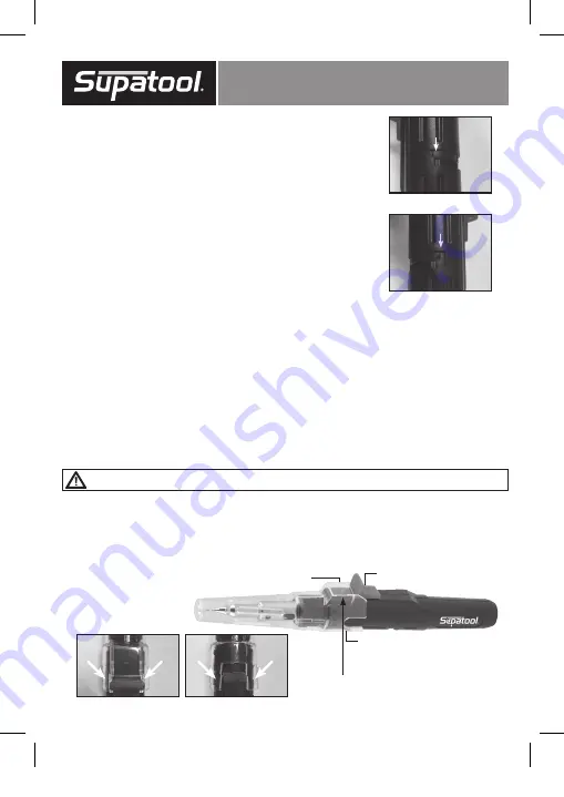
7. INSTALLING PROTECTIVE CAP
WARNING!
:When installing PROTECTIVE CAP (11), ensure the unit has had sufficient time to cool down
before installing!
1.
Ensure that CONTINUOUS LOCK (10) is in the “OFF” position.
2.
Align and slide the PROTECTIVE CAP (11) apertures beside the IGNITER SWITCH/STAND (7) (Fig 5)
and CONTINUOUS LOCK (10) (Fig 6), ensuring the LOCK OFF BUTTON (6) is covered by the SWITCH
SAFETY ENCLOSURE (12) of the PROTECTIVE CAP (11), as shown in the picture below (Fig 7).
3.
Ensure that entire tip assembly is fully covered by the PROTECTIVE CAP (11) .
(Fig 3)
(Fig 4)
IGNITER SWITCH
SAFETY LOCK OFF ENCLOSURE
CONTINUOUS LOCK
(Fig 5)
(Fig 6)
(Fig 7)
LOCK OFF BUTTON (6) COVERED BY
SWITCH SAFETY ENCLOSURE (10)
S15005 manual FA2 A6 pages.indd 5
6/07/2017 3:06 PM


