background image

[email protected]

www.suntechleds.com

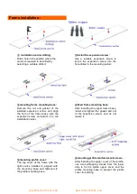
Frame installation :

mounting profile reinforcement screws:

After installing the upper cover of the profile,

use two self-tapping screws from the lower

side to fix the profile upper cover and the

profile mounting base to prevent the profile

cover from falling.

installation carrier drilling:

Drill a hole in the position where the

carrier is required to be drilled by

selecting a suitable drill bit;

Install the expansion screw:

Use a suitable expansion screw to

knock the expansion screw into the

hole drilled in the mounting carrier;

mounting frame mounting base:

Remove the nut and gasket of the

installed expansion screw, and align

the hole of the frame base with the

expansion screw and attach it to the

installation carrier;

fixed frame mounting base:

After installing the upper frame base,

install and tighten the gasket and nut

of the expansion screw, and do not

loosen it;

mounting profile cover:

The top cover of the frame with the

light source installed is aligned with

the mounting base and fastened to

the profile mounting base;

Summary of Contents for SPA030

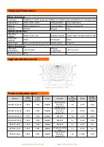
Page 1: ...cted by the national standard flexible cable which can be bent and deformed at will and supports the installation of special shaped façade The product spacing and color can be customized it is suitable for large area display or lighting of building facades bridges and skylights Features A new generation of TTL serial technology design Standard DMX512 Control Protocol Industry leading wireless butt...

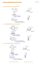
Page 2: ...n customized architectural lighting sales suntechleds com www suntechleds com 2 Base installation ball cover measurement 3 Frame installation flat cover measurement 4 Frame installation ball cover measurement ...

Page 3: ...ectric grade Class III Other parameters Operating temperature 20 C to 50 C Storage temperature 40 C to 70 C Protection level IP66 Light distribution curve Model Light source quantities Light source Color Control DC Operating Voltage Power White light light intensity SPA030 01AU 01 1PCS 3535 RGB W Dual channel Real time backup TTL 12V 0 3W 2 5cd SPA030 01AU 02 1PCS 3535 RGB W Dual channel Real time...

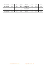
Page 4: ...m SPA030 03AE 3PCS 3535 RGB W DMX512 12V 0 72W 7 5cd SPA030 03XT 3PCS 5050 RGBW Single line serial TTL 12V 1 0W 12cd SPA030 04AU 4PCS 3535 RGB W Dual channel Real time backup TTL 15V 0 9W 10cd SPA030 04AE 4PCS 3535 RGB W DMX512 15V 0 9W 10cd ...

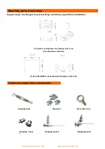
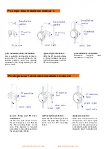
Page 5: ...by screw fixing wire fixing support frame installation Commonly used wire accessories Frame installation measurement drawing unit mm PC single mounting base size drawing unit mm two installation methods 吊码 Hanging hook Clip head Steel wire loop Hanging head 1 Hanging head 2 Hanging head 3 Cover Base ...

Page 6: ...ck into the PC mounting base installation is completed Schematic diagram after installation is complete adjustment pitch After the ins tal lati on is completed the pixel light pitch can be fine tuned to ensure that the point source is installed neatly schematic diagram after installation wire fixing and PC base installation Fix the two ends of the wire to the mounting base and then fix the PC moun...

Page 7: ...it Install the expansion screw Use a suitable expansion screw to knock the expansion screw into the hole drilled in the mounting carrier mounting frame mounting base Remove the nut and gasket of the installed expansion screw and align the hole of the frame base with the expansion screw and attach it to the installation carrier fixed frame mounting base After installing the upper frame base install...

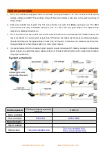
Page 8: ...ub control are connected by CAT5 twisted cables the maximum distance of each section is less than 120 meters the maximum transmission distance between the sub controller and the signal adaptor is less than 120 meters In this case the maximum distance from the signal adaptor to the first pixel light is no more than 2 meters 4 It is recommended that the maximum point spacing should not exceed 2 5 me...

Page 9: ...t be cut off during wiring to prevent people from getting an electric shock or damaging the lamp 4 When the external power cord is connected the corresponding measures of waterproofing and water leakage must be taken 5 The male and female waterproof protective covers for the products shall not be removed before the products are installed and connected 6 Quality Assurance Under normal conditions of...

Reviews: