


Install your machine in an appropriate environment and with adequate electrical supply. Failure to follow the
directions may result in machine malfunction.
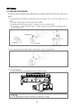
2-1) ENVIRONMENT
1) Temperature:
(1) 15~40°C (59~104°F) when machine is in operation
(2)
−
25~55°C (-13~131°F) when the machine is not in operation
2) Humidity: 45~90% (relative)
3) Grounding: Ensure the electricity is properly grounded.
4)
Close any doors and windows near the machine to prevent direct light, dust, and humidity.
5)
Foundation under the machine must be strong enough to support the weight of the machine.
=> It is recommended to use the SWF stand.
2-2) ELECTRICITY
Check if the input voltage of the machine is in the right range of the voltage supply before installing or operating
the machine. The input voltage is as follows:
1) Input voltage (adjust when installing): 100V, 110V, 120V, 200V, 220V, 240V
2) Allowed range of voltage: within 10% of the voltage set.
3) Electric capacity and Minimum input voltage: 600VA (400W)
4) Insulation resistance: over 10M ohms (measured with 500V insulation tester)
Warning
• Check the voltage supply where the machine will be installed.
• Install the cable away from the operator
’
s work space to prevent accident or injury.
INSTALLATION AND MACHINE ASSEMBLY
CHAPTER
2
[ Caution ]
• Do not let moisture drops on the machine.
• Provide air conditioning to control humidity and to eliminate dust and corrosion.
Danger
Properly ground the machine to avoid a possibility of electric shock. Use three-wire grounding
(grounding resistance below 100 ohms).
·KX-Single Head
12
Summary of Contents for SWF/KX Series
Page 8: ...A WARNING 1 7 Contents of Warning Stickers 8 ...
Page 11: ...KX Tubular 1 2 Placement of Warning Stickers Front From top 11 ...
Page 17: ... Frame support plate mounting hole location 17 ...
Page 28: ...4 4 UPPERTHREADING Upper thread stand 28 ...
Page 35: ...Hook Guide rail to the take up lever Movable blade Fixed blade 35 ...
Page 43: ...BLOCK DIAGRAM CHAPTER 6 KX Single Head 43 ...
Page 44: ... KX Tubular 44 ...


