background image

18

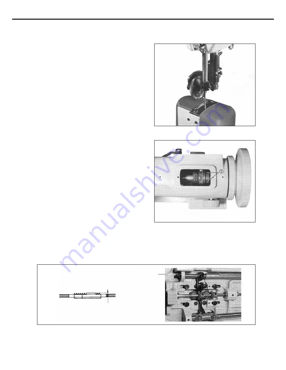
9) Adjusting timing of needle and feed dog

As in the figure, it is normal that the upper part of feed dog
goes down and the needle hole meets the upper part of needle
plate. If not, loosen the feed cam screws 

and move the cam

position right and left to the proper match. If gear moves faster
than needle, turn the feed cam to the opposite direction of the
machine rotation. If t gear moves slower than needle, rotate to
the proper match.

[Figure 19]

[Figure 20]

10) Adjusting height of feed dog

The normal adjustment is as follows. Turn pulley to place feed dog at the height point. And loosen lifter crank clamp screw

to

move the crank up and down. After that,  make the crank protrude 1mm in parallel with the upper needle plate and fix the gear.

[Figure 21]

About 1mm

Summary of Contents for KM-815 KM-825

Page 1: ...proper use of the machine thoroughly read this manual before use 2 Keep this manual in a safe place for future reference in case the machine breaks down User s Manual KM 815 Series KM 825 Series High post High speed one two needle sewing machine M MM ME E 0 05 50 05 50 09 9 ...

Page 2: ... functions high performance powerful operation enhanced durability and more sophisticated design to meet a number of user s needs 2 Please read this user s manual thoroughly before using the machine Make sure to properly use the machine to enjoy its full performance 3 The specifications of the machine are subject to change aimed to enhance product performance without prior notice 4 This product is...

Page 3: ... tension C Adjusting the thread take up spring tension 6 Adjusting roller presser foot height and pressure 16 A Adjusting the height of the presser foot B Adjusting the pressure of the presser foot 7 Rotating roller shaft 17 8 Adjusting stitch length 17 9 Adjusting timing of needle and feed dog 18 10 Adjusting height of feed dog 18 11 Adjusting timing of needle and hook 19 A Adjusting clearance be...

Page 4: ...hall be observed strictly Otherwise the user will be killed or suffer severe physical injuries Instructions here must be observed or the user could suffer fatal or severe physical injuries Instructions here should be observed or the user could face physical injuries or mechanical damages Danger The meaning of symbols This symbol means a must not This symbol means that an electric shock may be caus...

Page 5: ...y to occur according to the environment in which the machine is being installed Therefore the following preconditions should be fulfilled ⓐ Please keep the order from top to bottom when unpacking the package Especially mind that the nail on the boxes ⓑ Because machines are apt to be contaminated and corroded by dust and moisture you should install the climate controller and should clean the machin...

Page 6: ...n threading the needle or before checking after sewing be sure to stop the machine ⓗ Don t switch on the power supply with the foot on the pedal ⓘ Don t run the machine when the cooling fan are not running Be sure to clean the air filter in the control box once a week ⓙ If possible keep off from the strong electronic wave like a high frequency welding machine 1 4 Machine Operation Warning Warning ...

Page 7: ... Be sure to wait at least 360 seconds before opening this cover after turn off main switch and unplug a power cord 고압 전류에 의해 감전될 수 있으므로 커버를 열 때는 전원을 내리고 전원 플러그를 뽑고 나서 360초간 기다린 후 여십시오 CAUTION 경 고 Do not operate without finger guard and safety devices Before threading changing bobbin and needle cleaning etc switch off main switch 손가락 보호대와 안전장치 없이 작동하지 마십시오 실 보빈 바늘교환시나 청소전에는 반드시 주전원의 스위치를 꺼 주십시오 CAU...

Page 8: ...LLER PRESSER FOOT GENERAL PRESSER FOOT SLIDE HOOK COVER HINGE HOOK COVER HEAVY MATERIALS 2 DP 5 19 MAX 3 000 S P M MAX 5mm 33 4mm 61 5mm 7mm 11mm 178mm DROP OILER ASENDING OF PRESSUER FOOT MANUAL KNEE LIFT ROLLER PRESSER FOOT GENERAL PRESSER FOOT 1 16 3 32 1 8 3 16 1 4 3 8 2 Clutch motor MODEL HEC 1701 HEC 1703 HEC 1705 HEC 1706 VOLT ONE PHASE 220V THREE PHASE 220V 380V THREE PHASE 220V ONE PHASE ...

Page 9: ...teps down on the pedal with the plug in the machine will start automatically and can cause physical injuries Connect the ground earth wire An unstable connection may result in an electric shock or a malfunction Place the belt cover on top of the machine Use both hands when bending the machine backwards or returning it to the normal position Using only one hand can lead to severe hand injuries due ...

Page 10: ...10 2 Installation of machine head After fixing the machine head hinge into the bed holes with fixing screw and rubber hinge stand the machine on the rubber hinge and the rubber cushion Figure 2 ...

Page 11: ...with your eyes or skin Inflammation may be caused otherwise Never drink lubricants since they can cause vomiting or diarrhea Keep out of the reach of children Operate the machine only after adding oil when the machine is being used for the first time or has been left unused for a long time 3 Lubrication As can be seen in figure 3 be sure to supply oil into the oil holes marked red and the oil hole...

Page 12: ...ing insert the front part of belt cover B into the groove of belt cover A and then fasten the back part of it by using the clamp screw Figure 5 4 Adjustment of belt tension After installing the motor loosen the fixing nuts up and down and tension will be created to the belt due to motor falling by gravity Fasten the fixing nut initially and then fasten the fixing nut tightly Figure 4 ...

Page 13: ...ing machine only after the motor has come to a complete stop 1 Inserting needle As can be seen in figure 6 move the needle upper end so that it directly touches the upper side of the stopper hole when the groove of the needle is facing inward Then use the fixing screw to fix the position of the needle Figure 6 Stopper hole Needle groove Left and Right 2 Removing bobbin Place the needle in the high...

Page 14: ... hook After that lay down the bobbin holder and then close the hook cover on the right and left Figure 8 Caution Turn off the power switch when routing the upper thread It the operator mistakenly steps on the pedal the machine will start automatically and can cause physical injuries When using the clutch motor be aware that the motor will continue to rotate for a while after the power is switched ...

Page 15: ...igure 13 turning the tension adjustment nut of the hook clockwise makes the lower thread tension stronger and counterclockwise makes it weaker C Adjusting the thread take up spring tension a Adjusting the thread take up spring stroke As in Figure 14 loosen the fastening screw and turn the stopper bushing of the thread take up spring clockwise to make the stroke smaller and counter clockwise to mak...

Page 16: ...technicians or agent 6 Adjusting roller presser foot height and pressure A Adjusting the height of the presser foot Loosen the pressure adjustment screw and the presser bar bracket fastening screw and lift the presser bar lifter Make the distance between the upper side of the needle plate and the lower side of the presser foot 7mm Then tightly fasten the bracket fastening screw Be sure that the pr...

Page 17: ...ft Then there will be some space to exchange the gauge C To restart hold the roller presser foot bracket guide and turn it to the right direction Figure 17 8 Adjusting stitch length As in Figure 18 the number marked in the stitch length adjusting dial indicates the stitch width by mm By moving left or right set to the desired number Figure 18 ...

Page 18: ...r moves faster than needle turn the feed cam to the opposite direction of the machine rotation If t gear moves slower than needle rotate to the proper match Figure 19 Figure 20 10 Adjusting height of feed dog The normal adjustment is as follows Turn pulley to place feed dog at the height point And loosen lifter crank clamp screw to move the crank up and down After that make the crank protrude 1mm ...

Page 19: ...needle and hook A Adjusting clearance between needle and edge of hook Loosen the hook base clamp screw and the lower shaft gear clamp screw And then move hook base right or left to make the clearance 0 05mm wide B Adjusting ascending level of needle bar Loosen the lower shaft gear clamp screw and raise needle 2 4mm from the lowest point When is done move the gear right and left to put the edge at ...

Page 20: ...e power 1 Open the hook cover Loosen post cover clamp screw 2 Loosen the right and left hook base clamp screw 3 Raising the presser lifter rotate the roller right or left 4 Remove the needle 5 Disassemble the needle holder 6 Disassemble the needle guide for roller presser foot 7 Disassemble the needle plate 8 Disassemble the feed dog B Assembly order After assemble in reverse order of disassembly ...

Page 21: ...the needle inserted is wrong Bent needle or broken needle tip Wrong threading Bad timing of needle and hook Bad timing of needle and hook The gap between needle and hook is inadequate The length of the remaining upper thread is too short The spring is not strong enough to pull out the lower thread Too tight upper thread tension Too weak upper thread tension Tension of upper thread is too weak Tens...

Reviews: