background image

10

4. Return the machine to its original position

1) Clear the table of tools.
2) With the right hand, return the machine to its original

position, while grabbing sideboard with the left hand. 

[ Figure 4 ]

[ Figure 5 ]

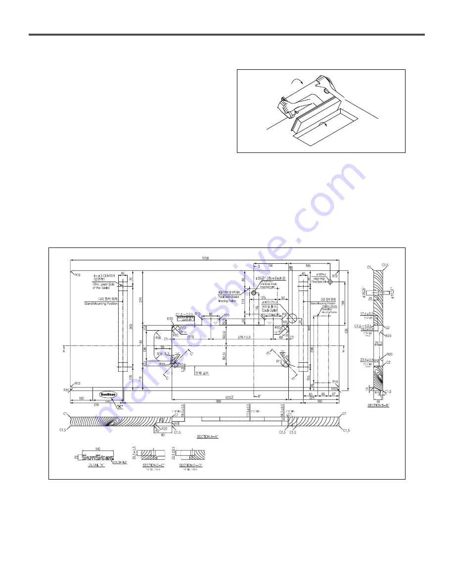
4-1. Table drawing

Please use the table provided by Sunstar. When using self-made table , the thick of table should be more than 40mm. Please use
table strong enough to sustain the weight of the machine.

1. Table Drawing

Summary of Contents for KM-2300

Page 1: ... 2 KEEP THIS MANUAL IN SAFE PLACE FOR REFERENCE WHEN THE MACHINE BREAKS DOWN USER S MANUAL KM 2300 Series D Diir re ec ct t D Dr riiv ve e H Hiig gh h S Sp pe ee ed d 1 1 N Ne ee ed dlle e L Lo oc ck k S St tiit tc ch h M Ma ac ch hiin ne e w wiit th h a an n A Au ut to om ma at tiic c T Th hr re ea ad d T Tr riim mm me er r M MM ME E 0 05 50 06 62 27 7 ...

Page 2: ......

Page 3: ... functions high performance powerful operation enhanced durability and more sophisticated design to meet a number of user s needs 2 Please read this user s manual thoroughly before using the machine Make sure to properly use the machine to enjoy its full performance 3 The specifications of the machine are subject to change aimed to enhance product performance without prior notice 4 This product is...

Page 4: ...run Pedal operation 16 4 5 Installation KM 2310 Series 16 5 Preparations for sewing 17 5 1 Installing needle 17 5 2 Removing bobbin case 17 5 3 Winding lower thread 18 5 4 Installing bobbin case 18 5 5 Inserting upper thread 19 5 6 Using knee lifter pad 19 6 Sewing 20 6 1 Sewing 20 6 2 Back tack reverse sewing 20 6 3 Adjusting thread tension 21 6 3 1 Lower thread tension 21 6 3 2 Upper thread tens...

Page 5: ... height 28 8 4 Adjusting wiper 28 8 5 Adjusting needle bar height 29 8 6 Adjusting height and slope of feed dog 29 8 7 Needle and conveying timing 30 8 8 Needle and hook timing 30 8 9 Adjusting trimming time 31 8 10 Adjusting and replacing knife 31 8 10 1 Adjusting fixed knife 31 8 10 2 Replacing movable knife 32 8 10 3 Replacing fixed knife 32 8 11 Adjusting bobbin stopper 33 8 12 Adjusting oil f...

Page 6: ...oden boxes ⓑ Dust and moisture stains and rusts the machine Install an airconditioner and clean the machine regularly ⓒ Keep the machine out of the sun ⓓ Leave sufficient space of more than 50cm behind and on the right and left side of the machine for repairing ⓔ EXPLOSION HAZARDS Do not operate in explosive atmospheres To avoid explosion do not operate this machine in an explosive atomsphere incl...

Page 7: ...as the control box ⓖ Stop the machine before threading the needle or checking after work ⓗ Do not step on the pedal when turning the power on ⓘ If possible install the machine away from source of strong electrical noise such as high frequency welding machines 1 4 Operating machine Warning Notice Warning Keep motor cover in place before operating turn off power before inspecting or adjusting 1 5 Sa...

Page 8: ...경 고 Hazardous voltage will cause injury Be sure to wait at least 360 seconds before opening this cover after turn off main switch and unplug a power cord 고압 전류에 의해 감전될 수 있으므로 커버 를 열 때는 전원을 내리고 전원 플러그를 뽑 고 나서 360초간 기다린 후 여십시오 Caution 1 2 1 7 Contents of marks Warning Caution mark is attached on the machine for safety When you operate the machine follow the directions on the mark 1 6 Caution mark po...

Page 9: ...per Presser bar lifting lever Reverse button Presser foot Control box Knee lifting pad Power switch Oil window Reverse lever Stitch length dial Pulley Program unit Thread stand ass y Safety Devices Thread take up cover Finger guide Motor cover ...

Page 10: ...neral materials Light materials General materials Heavy materials General materials Heavy materials 3 500spm 4mm 4 000spm 5mm 4 000spm 4mm 5 000spm 5mm 4 000spm 4mm 5 000spm 5mm 5 000spm 4 500spm 4 500spm 5mm 33 4mm 1 1 2mm 0 75 0 85mm 29mm 30 7mm 30 7mm 30 7mm 30 7mm 0 75 0 85mm 1 1 2mm 33 4mm 29mm 29mm 5mm 5 5mm 15mm 15mm Option No Lubrication Needle Bar No Lubrication Micro Lubrication Type Aut...

Page 11: ...d can lead to severe hand injuries due to the weight of the machine 1 Installation place 1 Do not install the machine near television radio or telephone or the operation of machine can be interfered with by the noise from the appliances 2 Connect the ground earth wire An unstable connection may result in malfunction 2 Machine delivery 1 There should be two people to move the machine as in the Figu...

Page 12: ... machine to its original position while grabbing sideboard with the left hand Figure 4 Figure 5 4 1 Table drawing Please use the table provided by Sunstar When using self made table the thick of table should be more than 40mm Please use table strong enough to sustain the weight of the machine 1 Table Drawing ...

Page 13: ...le with four bolts Figure 7 2 Pedal switch and connecting rod 1 Attach pedal switch to pedal switch bracket with four bolts 2 As in the Figure attach pedal switch bracket to the lower part of table 3 Connect one end of the connecting rod with pedal switch and the other end with pedal and then adjust length of the rod ...

Page 14: ...ead hinge rubber c into four holes of oil pan 4 Place safely oil pan assembled with cushion rubbers into the rectangular hole on the table 5 Insert knee lifting support cap into oil pan s projecting hole as in the figure 4 Hinge Rubber 1 As in the figure assemble two hinge rubbers on the table 2 As in the figure fix the hinge rubbers with nails Figure 8 Figure 9 ...

Page 15: ...utting hinges on the hinge bed rubber safe and sound 3 Insert the machine body sustaining pole into table completely If the pole is not inserted completely that may cause accidents because the pole cannot sustain the weight of machine body firmly when the body bent backwards 7 Program Unit 1 As in the Figure combine program unit to bracket with three screws 2 Attach the combined bracket to the upp...

Page 16: ...pan And then fix it with bolt 2 Loosen bolt to adjust position of knee lifter pad Figure 15 10 Adjusting height of Presser Foot 1 Turn pulley to place feed dog in the lower part of needle plate 2 When presser foot is up make presser foot down by lowering presser bar lifting lever 3 Adjust the position of presser foot by using screw Figure 14 Figure 13 ...

Page 17: ...ly wash it with running water and see a doctor Never drink lubricants since they can cause vomiting or diarrhoea Go to see a doctor if you mistakenly drink lubricant Keep the oil out of the reach of children Keep the oil away from heat Operate the machine only after supplying oil when the machine is used for the first time or has been left unused for a long time Only use genuine lubricant of this ...

Page 18: ...r pressing pedal the position of to D and then replacing pedal to the position of A needle will stop higher than the upper surface of needle plate after trimming Figure 19 4 5 Installation KM 2310 Series 1 Installing magnet for chip metal powder removal 1 Take out the magnet for chip metal powder removal from the accessory box and attach it to inside the oil fan If the sewing machine is operated w...

Page 19: ... machine will start automatically and can result in physical injuries 1 Turn the pulley of machine to raise needle bar to its highest position 2 Unfasten the fixing screw 3 As in the figure insert needle straight to the end with the needle s long groove facing left and fasten the fixing screw firmly 1 Place needle at the upper part of needle plate by turning pulley 2 Remove bobbin case by pulling ...

Page 20: ...obbin winder knife To adjust the amount of bobbin winding loosen screw and adjust bobbin winder adjusting plate Caution Make sure that thread should be regulated to wind 80 of bobbin capacity 5 4 Installing bobbin case Caution When installing bobbin case make sure to turn off the power Pressing pedal by mistake may result in physical injuries or mechanical damages 1 Turn pulley to place needle at ...

Page 21: ...al injuries 1 Place the thread take up at its the highest position by turning pulley before inserting the upper thread so that it becomes easy to insert it and prevent it from falling out when the machine starts to operate 2 The adequate length of upper thread extending from the needle hole is 35 40mm Figure 24 5 6 Using knee lifer pad 1 Pressing knee lifter pad to the right will move presser foot...

Page 22: ...replacing bobbin or needle When the machine not in use or the operator leaving the work place 6 1 Sewing 1 Press ON button of power switch 2 Lamp on the program unit turns on and machine is ready to operate 3 Control sewing conditions by using program unit See user s manual of Fortuna IV 4 Step on the pedal to operate 6 2 Back tack reverse sewing 1 Pressing the reverse switch or reverse lever will...

Page 23: ... is too weak Make upper thread tension strong or make lower thread tension weak Make upper thread tension weak or make lower thread tension strong 6 3 1 Lower thread tension 1 Adjust tension by turning tension control screw to the extent that bobbin case falls by gravity when holding the end of thread 6 3 2 Upper thread tension 1 Adjust upper thread tension after adjusting lower thread tension to ...

Page 24: ...t and decreasing the tension will make it long 6 5 Adjusting presser foot pressure Figure 30 6 5 1 Presser foot pressure 1 Make the presser foot pressure as weak as possible But as weak as for sewing material not to slide 2 Unfasten the pressure adjusting nut 3 Turn the pressure adjusting screw to adjust presser foot pressure 4 Fasten the pressure adjusting nut Figure 31 Sewing style Causes Correc...

Page 25: ...ts since they can cause vomiting or diarrhea Go to see a doctor if you mistakenly drink lubricant Keep the oil out of the reach of children Keep the oil away from heat Use both hands when bending the machine backwards or returning it to the original position Using only one hand can lead to severe hand injuries due to the weight of the machine 7 1 Daily cleaning 7 1 1 Cleaning 1 Raise presser foot ...

Page 26: ...ry box of the machine 1 Disassemble the air exhaust rubber cap 2 Pour lubricant so that oil surface is in the middle of MAX and MIN carved lines on the oil window on the gear box cover Be careful not to make lubricant overflow 3 Assemble the rubber cap and push it down completely Caution Bend the machine body backward to check the oil flow in the gear box Since the height of oil in the oil window ...

Page 27: ...he upper part of oil gauge is between two orange carved lines 3 If the upper part of oil gauge is under the lower carved line supply lubricant by referring to 4 3 supplying oil 7 1 3 Checking 1 When needle is deformed or the end of needle is damaged change the needle 2 Check if upper thread is inserted correctly Refer to 5 5 Inserting upper thread 3 Run trial sewing Figure 37 Figure 36 ...

Page 28: ...ease to the place where the grease needs to be applied 5 If the grease is used up only buy and use the Sunstar s genuine grease Figure 38 GP 001994 GP 001992 7 2 3 How to supply grease 1 Turn off the power 2 Remove the screw 3 Supply grease until grease goto over arrow mark 4 Fasten the screws 5 Turn polley 5 10 times by hand 6 Wipe flowed grease 7 Turn on the power and start sewing 7 2 2 Greaging...

Page 29: ...sting thread take up spring 8 1 1 Position of thread take up spring It is standard that thread take up spring is at the place where the spring s movement range is 6 8mm from the upper surface of thread routing plate with presser foot descending A and G type For B and H type 4 6mm is standard 1 Lower presser foot 2 Loosen fixing screw lightly 3 Adjusting position by turning thread control device 4 ...

Page 30: ...st presser foot pressure with pressure adjusting screw Fasten the nut Figure 42 8 4 Adjusting wiper 1 Turn the pulley manually and stop turning when it reaches at highest position of the thread take up lever 2 Loosen the two wiper shaft fixing screws on the wiper base and press the connecting link with the hand Then adjust the wiper shaft so that the gap between the wiper and the needle is about 2...

Page 31: ...ion 2 Bend the machine backward 3 Loosen fixing screw and fixing screw lightly 4 Adjust feed dog height and slope by turning lifter crank eccentric shaft and eccentric shaft of feed dog bed crank 5 Refer to the right side figure to see movement direction of feed dog bed according to rotation direction of each eccentric shaft 6 After finishing adjustment fasten fixing screws and by pushing eccentri...

Page 32: ... lifter cam 4 The standard timing is when lifter shaft carved line is aligned with the middle line on the bearing cover carved line 5 Turning the lifter cam in the direction of will make conveying timing fast It is generally used to prevent puckering 6 Turning the lifter cam in the direction of will make conveying timing slow It is generally used to enhance the thread tightening 8 8 Needle and hoo...

Page 33: ... roller driving part on the trimming cam touches the roller Then tighten the trimming cam fixing screw 5 Connect the return spring Figure 50 8 10 Adjusting and replacing knife 8 10 1 Adjusting fixed knife 1 First loosen the fixed knife tension adjusting nut with a wrench box and then loosen the tension adjusting screw 2 Adjust the tension adjusting screw of the fixed knife when the movable knife e...

Page 34: ...reverse order to assemble Figure 52 8 10 3 Replacing fixed knife 1 To replace the fixed knife loosen the hook holder fixing screw as in Fig 53 remove the washer and hook holder and then unfasten the fixed knife fixing screw 2 Follow these instructions in reverse order to assemble Figure 53 3 If the edge of the fixed knife is worn make sure to grind the knife edge with an oil grindstone as shown in...

Page 35: ...meets the bobbin stopper adjustment baseline that is marked on the top Loosen the bobbin catcher fixing screw and adjust the bobbin stopper so that the contact surface of the bobbin stopper lightly touches the center of the projecting part of the bobbin Once the operation is completed check to see whether the bobbin stopper springs back lightly Figure 56 8 12 Adjusting oil flow in hook KM 2300M S ...

Page 36: ...el Resulting Oil Tape 3 10mm More 8 13 Oil Supply Adjustment KM 2310 Series 1 Adjusting oil supply to thread take up lever 1 As in the figure when the punched mark on the oil volume adjusting pin head is aligned with the hole of the needle bar crank the oil supply volume will become maximum As the oil volume adjusting pin is turned left or right and becomes closer to the edge of the crank cam plat...

Page 37: ...over fixing screw and remove the solenoid cover 4 If the solenoid shaft is moved left and the fixing screw is tightened when the solenoid crank shaft fixing screw is loose the lifting amount of the presser foot grows smaller and if it is moved right and the fixing screw is tightened the lifting amount of the presser foot grows bigger 5 Assemble the cover back after the adjustment is completed The ...

Page 38: ...eedle tip Thread passing at wrong position Wrong timing of needle and hook Wrong timing of needle and hook Wrong timing of needle and hook Remaining length of upper thread is short Due to bobbin racing during trimming lower thread dropping from bobbin case becomes too short to go up Racing proof spring of bobbin case Unable to lift lower thread due to weak take up lever spring Take up lever spring...

Page 39: ...f upper thread Check thickness of needle Adjust the up stop position of needle 7 Upper thread is pulled out when sewing commences Too tight upper thread tension Too loose lower thread tension Too weak upper thread tension Too strong lower thread tension Reduce tension of upper thread Increase tension of lower thread Increase upper thread tension Decrease tension of lower thread Upper thread does n...

Reviews: