background image


TROUBLESHOOTING 

PROBLEM 

CAUSE 

SOLUTION 

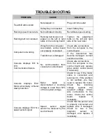
Treadmill will not start 

 
Not plugged in 


Plug cord into outlet 

Safety Key not inserted 

Insert Safety Key 

Running speed inaccurate 

Not calibrated correctly 

Recalibrate speed setting


Running belt not centered 

Running belt tension not 
proper  on  the  left  or  right 
sides of the running board 

Tighten 

the 

adjustment 

bolts  on  the  left  and  right 
side of the rear roller 


Computer not working 

Wires from the computer 
And  bottom  control  board 
not properly


connected.


Check wire connections 
from  the  computer  to  the 
control board 

Transformer is damaged 

If  the  transformer  has 
become  damaged,  contact 
customer service 

Console  displays  E01  & 
E13:  
Communication failure 

No  communication  from 
console to control board 

Check wire connections 
from  the  computer  to  the 
control  board  and  replace 
wires  and/or  control  board 
if necessary 

Console 

displays 

E02: 

Motor abnormality or Burst 
clash protection 

Motor 

cable 

is 

disconnected  or  incoming 
voltage  is  lower  than  50% 
of the required voltage. 

Check  to  see  if  the  motor 
cable  is  connected  and 
reconnect it. If the problem 
is  not  rectified,  you  may 
need  to  replace  the  motor.  
Check 

the 

incoming 

voltage 

against 

the 

required  voltage.  Check 
wire  connections  to  the 
motor.  Check  the  control 
board, 

replace 

if 

necessary. 

Console  displays  E03:  No 
speed sensor signal 

Speed 

sensor 

signal 

cannot  be  received  by  the 
control board. 

Check that the sensor wire 
is  properly  connected  and 
replace  wire  if  damaged. 
Check 

to 

see 

if 

the 

magnetic 

sensor 

is 

damaged  and  replace  if 
necessary.  

22 

Summary of Contents for SF-T7512

Page 1: ...ADMILL SF T7512 USER MANUAL IMPORTANT Read all instructions carefully before using this product Retain owner s manual for future reference For customer service please contact support sunnyhealthfitnes...

Page 2: ...or adult use only 4 Use the equipment on a solid flat level surface with a protective cover for your floor or carpet To ensure safety the equipment should have at least 2 feet of free space all around...

Page 3: ...ndrail when making changes with the controls 7 A safety key is provided with this equipment and should be used in case of emergency Operational functions can only be done while the safety key is inser...

Page 4: ...EXPLODED DRAWING 3...
Page 5: ...net 1 C29 Plastic pad 4 B10 Turning bushing 4 C30 Safety key bracket 1 B11 Copper sheet 1 C31 Safety key 1 B12 Allen wrench 5mm 1 C32 Transport wheel plug 2 B13 Spanner with screw driver S 13 14 15 1...

Page 6: ...5 AC single wire 350mm 1 D56 Bolt M5 16 11 D26 Wire 1 500mm 1 D57 Bolt M5 8 9 D27 Wire 2 350mm 1 D58 Screw ST4 2 30 2 D28 Wire 3 350mm 1 D59 Screw ST4 2 30 4 D29 Filter 1 D60 Screw ST4 2 12 15 D30 Ind...

Page 7: ...ecification Qty No Description Specification Qty A02 Main Frame 1 D46 Bolt M8 50 2 E Console base 1 D50 Bolt M8 15 6 B12 5 Allen wrench 5mm 1 D64 Lock washer 8 8 B13 Wrench with Screw Driver S 13 14 1...

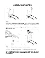
Page 8: ...Left Upright Tubes No A05 upwards See Figure 1 Fix the Left Upright Tube No A05 to the Base Frame No A01 Use 1 Bolt No D46 and 1 Lock Washer No D64 to attach the side and 1 Bolt No D50 and Lock Washer...

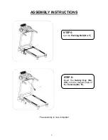
Page 9: ...e Base Frame No A01 Repeat the step above to attach the Right Upright Tube Cover No C09 to the Base Frame No A01 STEP 4 PLEASE SEEK ASSISTANCE FOR THIS STEP Connect the Top Signal Wire No D04 to the M...

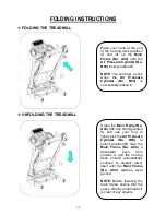
Page 10: ...ASSEMBLY INSTRUCTIONS The assembly is now complete STEP 5 Cut the Packing Belt No F STEP 6 Insert the Safety Key No C31 into the magnet area of the Console No E 9...

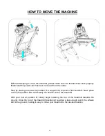
Page 11: ...der No B03 is successfully locked in Grasp the Main Frame No A02 with one hand position A and use your foot to lightly kick the Air Pressure Cylinder No B03 to unlock position B Give the Main Frame No...

Page 12: ...d at position A to support the top end of the treadmill Next place one foot at position B to hold steady the bottom end of the treadmill With your foot at position B slowly begin lowering the top of t...

Page 13: ...and ordinances CAUTION Improper connection of the equipment can result in risk of electric shock Check with a qualified electrician or serviceman if you are unsure whether the product has been proper...

Page 14: ...utomatically reset to the initial setting after 5 seconds When setting programs this window is shown as PI P15 U1 U3 and FAT 3 TIME Displays the running time from 0 00 18 hours When the count reaches...

Page 15: ...se the speed continually 6 INCLINE UP DOWN BUTTONS Press this button to adjust incline When the machine is running press the Up Down Buttons to increase or decrease the incline in increments of 1 time...

Page 16: ...tly pressing the START button will automatically start the running belt to the default running speed of 0 6MPH The other windows will begin counting upward from the default speed Pressing the SPEED ke...

Page 17: ...return to the current incline and speed After completing a program the system will beep and display END The machine will stop smoothly and automatically reset to the initial setting after 5 seconds P...

Page 18: ...ll operate at the preset speed and incline of your settings The whole program will be divided into 10 sections Each section will divide into 10 setting times for the exercise time and section will adj...

Page 19: ...medical use The Body Quality Index is suitable for both male and female NOTE Average Body Quality Index score is 20 25 Underweight Below 19 0 Normal 20 0 25 0 Overweight 26 0 29 0 Obesity 30 0 and ab...

Page 20: ...el comfortable you may slowly increase the speed When you are finished with your exercise press the STOP button or remove the magnetic end of Safety Key No C31 to stop the machine SAFETY LOCK Remove t...

Page 21: ...20 drifts from the center 1 If the Running Belt No 20 drifts to the right turn the adjusting bolt on the right side turn clockwise then turn the left adjustment bolt turn counter clockwise If the bel...

Page 22: ...able is recommended Light user less than 3 hours week once a year Medium user 3 5 hours week every six months Heavy user more than 5 hours week every three months NOTE oTo better maintain the treadmil...

Page 23: ...E13 Communication failure No communication from console to control board Check wire connections from the computer to the control board and replace wires and or control board if necessary Console displ...

Page 24: ...is damaged Restart the treadmill Check the incoming voltage to ensure it s correct Check the control board replace if damaged A moving part of the treadmill is stuck and therefore the motor is unable...

Reviews: