background image


No.


Description


Spec.


Qty.


No.


Description


Spec.


Qty.


69 

Control Board 


93 

Fixed Base Plate 


70 

Incline Motor 


94 

Bolt 

4.2*25 

71


Rotary Knob


2


95


Bolt


4.2*6.5


4


72


Fixed Tuning Plate


2


96


Bolt


4.2*30


2


73


Spring


1


97


Bolt


4.2*28


2


74


D Shape Pad


2


98


Bolt


ST4.2*13


22


75


Strengthen Tube


2


99


Bolt


2.9*9.5


4


76


Bolt


M10*42


1


100


Bolt


2.6*6 (front is 5


5


77


Bolt


M10*55


1


101


Lock Washer


10


2


78


Bolt


M10*45


2


102


Flat Washer


8


2


79


Bolt


M8*40


4


103


Spring Washer


8


2


80


Bolt


M8*16


4


104


Lock Washer


6


3


81


Bolt


M6*35


6


105


Spring Washer


5


2


82


Bolt


M6*25


2


106


Lock Washer


5


2


83


Screw Nut


M8


4


107


Silicone Oil


1


84


Screw Nut


M6


8


108


Transportation Wheel


2


85


Bolt


M8*2


4


109


Spring 


2


86


Bolt


M6*65


1


110


Oil Guide Plate 

Assembly


1


87


Bolt


M6*60


2


111


Handrail Nylon Gasket 


2


88


Bolt


M5*8 


3


112


Reverse Hook Buffer 

Pad


2


89


Bolt


4.2*19


16


113


Strengthen Tube 1


1


90


Bolt


4.2*12


5


114


Bolt 


4.8*19


5


91


Bolt


4.2*12


18


115


Bolt 


M8*25


2


92


Bolt


4.2*9.5


2


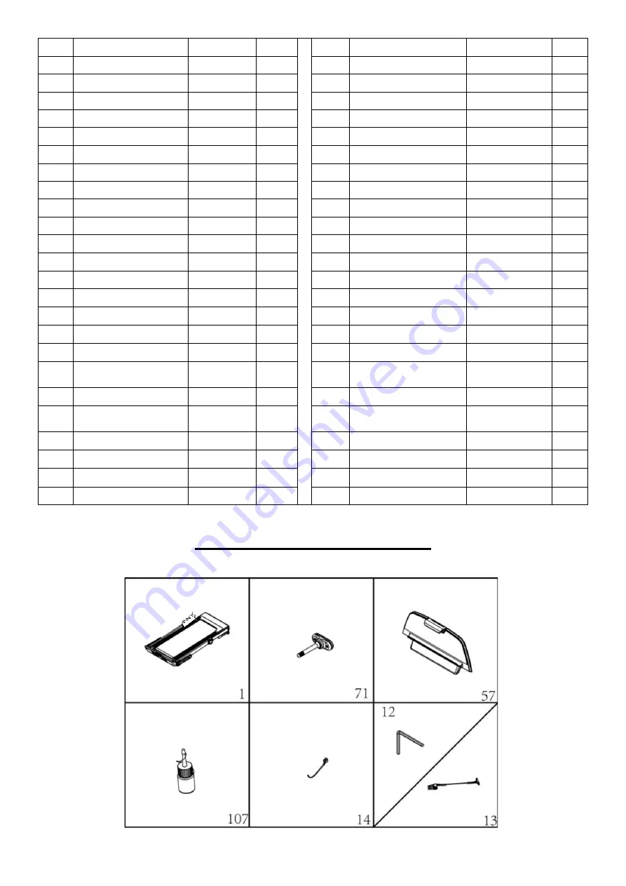
ASSEMBLY CONTENTS


When you open the carton, you will find the below parts inside. 


Summary of Contents for SF-T7951

Page 1: ...NUAL IMPORTANT Please retain owner s manual for maintenance and adjustment instructions Your satisfaction is very important to us PLEASE DO NOT RETURN UNTIL YOU HAVE CONTACTED US support sunnyhealthfi...

Page 2: ...o ensure safety the equipment should have at least 8 feet 240 CM of free space behind it and 2 feet 60 CM on each side Do not place the treadmill on any surface that blocks air openings To protect the...

Page 3: ...2 EXPLODED DIAGRAM...

Page 4: ...n Pad 8 15 Running Board 1 49 Handlebar Cap 2 16 Adjustment Wheel 2 50 Wheel Cover 2 17 Motor Top Cover 1 51 Cushion 2 18 Motor Bottom Cover 1 52 Brown Single Wire 1 19 Switch 1 53 Grounding Wire 1 20...

Page 5: ...Washer 8 2 79 Bolt M8 40 4 103 Spring Washer 8 2 80 Bolt M8 16 4 104 Lock Washer 6 3 81 Bolt M6 35 6 105 Spring Washer 5 2 82 Bolt M6 25 2 106 Lock Washer 5 2 83 Screw Nut M8 4 107 Silicone Oil 1 84...

Page 6: ...in order for us to accurately identify the part s needed The model number found on cover of manual The product name found on cover of manual The part number found on the EXPLODED DIAGRAM and PARTS LIS...

Page 7: ...69 STEP 1 Open the carton and remove all contents Place the Main Frame No 1 on level ground and ensure that you have a clean adequate workspace STEP 2 Hold up the Computer Frame Insert the 2 Rotary Kn...

Page 8: ...Right Handlebar No 6 No 7 to the horizontal position as shown on the left STEP 4 Insert the Tablet Bracket No 57 into the computer as shown on the left Attach the Safety Key No 13 onto the computer I...

Page 9: ...ating or repairing the unit The following timetable is recommended Light user less than 3 hours week every 2 months Medium user 3 5 hours week every 45 days Heavy user more than 5 hours week every mon...

Page 10: ...the Running Belt No 68 according to instructions below with Allen Wrench No 12 If the Running Belt No 68 drifts to the right remove the Safety Key No 13 turn the adjusting bolt on the right side 1 4...

Page 11: ...Pull up the treadmill as shown in picture A D For your safety please adjust this to the highest incline so that treadmill doesn t fall down The folding is complete NOTE Put the treadmill close to the...

Page 12: ...e top end of the treadmill Next place one foot at position K to hold the bottom end of the treadmill steady With your foot at K slowly tilt the top of the treadmill downward towards the ground Once th...

Page 13: ...codes and ordinances CAUTION Improper connection of the equipment can result in risk of electric shock Check with a qualified electrician or serviceman if you are unsure whether the product has been p...

Page 14: ...OGRAM BUTTON Press this button to choose program from manual mode P1 P15 MODE BUTTON When treadmill is in standby state press this button to choose any of the following Manual Mode Time Countdown Mode...

Page 15: ...utomatically The speed incline and next section will change When finishing the program the treadmill will stop smoothly and incline will return to 0 While running you can change the speed and incline...

Page 16: ...7 7 8 8 9 9 6 6 5 4 4 P08 SPEED 2 3 3 6 5 4 4 6 2 4 6 5 4 4 4 2 3 4 4 2 INCLINE 4 5 5 5 6 6 6 7 8 9 9 9 10 10 10 12 12 8 6 3 P09 SPEED 2 4 4 3 5 4 3 2 4 5 6 6 4 4 4 5 6 3 3 2 INCLINE 5 5 5 6 6 6 4 4...

Page 17: ...TART button to start the treadmill The treadmill will start at the default speed of 0 5 MPH Miles per hour Once you feel comfortable you may slowly increase the speed When you are finished with your e...

Page 18: ...If the speed sensor does not find signal check if the sensor signal light is shining or not If it is burned out change the signal light 2 Check if the speed sensor plug is connected well or if there i...

Page 19: ...18...
Reviews: