background image


Squat Exercise Trainer 

SF-A020052 


USER MANUAL 


IMPORTANT!

  Please  r

etain  owner’s  manual  for  maintenance  and  adjustment  instructions.  Your 

satisfaction is very important to us,

 PLEASE DO NOT RETURN UNTIL YOU HAVE CONTACTED 

US

[email protected] or 1- 877 - 90SUNNY (877-907-8669). 


Summary of Contents for SF-A020052

Page 1: ...MANUAL IMPORTANT Please retain owner s manual for maintenance and adjustment instructions Your satisfaction is very important to us PLEASE DO NOT RETURN UNTIL YOU HAVE CONTACTED US support sunnyhealthfitness com or 1 877 90SUNNY 877 907 8669 ...

Page 2: ...e equipment The equipment is designed for adult use only 4 Use the equipment on a solid flat level surface with a protective cover for your floor or carpet To ensure safety the equipment should have at least 2 feet 60 CM of free space all around it 5 Ensure that all nuts and bolts are securely tightened before using the equipment The safety of the equipment can only be maintained if it is regularl...

Page 3: ... 30 30 30 30 30 26 27 27 28 28 29 29 29 29 31 31 31 31 32 32 33 33 34 35 40 41 36 44 45 37 37 37 37 46 46 46 46 1 2 3 4 5 6 7 16 8L 8R 16 9 10 11 11 12 12 13L 13R 14 15 17 18 18 19 20 20 21 21 22 22 22 22 22 22 24 24 24 24 31 23 23 23 23 38 39 43 24 24 42 42 30 ...

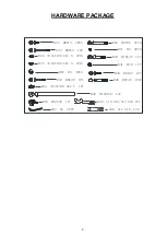
Page 4: ...4PCS 32 M8 55 2PCS 33 M8 65 1PC 29 Φ16 Φ8 5 1 5 4PCS 30 Φ16 Φ8 5 1 5 7PCS 31 M8 4PCS 40 M10 40 1PC 41 M10 1PC 36 M12 150 1PC 34 M8 40 1PC 44 Φ22 Φ8 5 1 5 1PC 45 M8 25 1PC 37 M8 4PCS 38 S17 S19 1PC 39 S13 S15 S17 S19 1PC 43 S6 2PCS 35 M12 20 1PC ...

Page 5: ...al 1 36 Bolt M12 150 1 13R Right Pedal 1 37 Nut M8 4 14 Hydraulic Cylinder 1 38 Spanner S17 S19 1 15 Seat 298 158 45 1 39 Spanner S13 S15 S17 S19 1 16 Foam Grip Φ25 2 40 Hex Socket Bolt M10 40 1 17 Meter 1 41 Nylon Nut M10 1 18 Handlebar End Cap Φ25 2 42 Exercise Band Φ5 580 2 19 Buffer Column Φ26 51 1 43 Allen Wrench S6 2 20 Inner Bushing 2 44 Washer Φ22 Φ8 5 1 5 1 21 Round Plug 2 45 Hex Socket S...

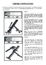
Page 6: ...tabilizer No 10 to Main Frame No 1 with 2 Carriage Bolts No 46 2 Arc Washers No 29 and 2 Nuts No 37 Tighten and secure with Spanner No 39 Attach Front Stabilizer No 9 to Front Support Tube No 2 with 2 Carriage Bolts No 46 2 Arc Washers No 29 and 2 Nuts No 37 Tighten and secure with Spanner No 39 Attach Hydraulic Cylinder No 14 to the u shaped seat on the top of Main Frame No 1 with 1 Hex Socket Bo...

Page 7: ... No 4 onto the Seat No 15 with 4 Hex Socket Screws No 25 and 4 Washers No 30 that were removed Tighten and secure with Allen Wrench No 43 Insert the Seat No 15 into the Seat Tube No 3 adjust the Seat No 15 to your desired position then tighten and secure with Triangle Knob No 35 STEP 4 Attach Pedal Connecting Tube No 6 into Middle Post Tube No 7 with 3 Hex Socket Screws No 25 and 3 Washers No 30 T...

Page 8: ...olt No 33 2 Washers No 30 and 1 Nylon Nut No 31 Tighten and secure with Allen Wrench No 43 and Spanner No 39 Align the Left Pedal No 13L with the left side of the Pedal Connecting Tube No 6 at 90 and gently insert the Left Pedal No 13L into the Pedal Connecting Tube No 6 Turn the Left Pedal No 13L counter clockwise as tightly as you can with your hand Then tighten and secure with Spanner No 39 Ali...

Page 9: ...st Tube No 7 with 2 Hex Socket Bolts No 32 2 Washers No 30 and 2 Nylon Nuts No 31 Tighten and secure with Allen Wrench No 43 and Spanner No 39 Insert the Meter No 17 into the Middle Post Tube No 7 STEP 7 Connect 2 Exercise Bands No 42 to the hooks on the Front Stabilizer No 9 then hang the 2 Exercise bands No 42 to Left Right Handlebars No 8L No 8R The assembly is complete 8L 17 8R 32 3031 3031 1 ...

Page 10: ...to the back of the Meter No 17 The installation is complete BATTERY REPLACEMENT 1 Press the buckle of battery cover on the back of the Meter No 17 then remove battery cover 2 Remove the 1 old AA battery in the battery case and install 1 new AA battery into the battery case on the back of the Meter No 17 Pay attention to the battery and poles before installing 3 Press the buckle of battery cover th...

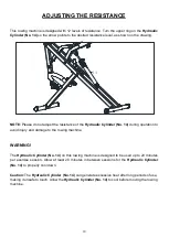
Page 11: ... 14 during operation to avoid injury and damage to the rowing machine WARNING The Hydraulic Cylinder No 14 on this rowing machine is designed to be used up to 20 minutes per exercise session Allow at least 20 minutes in between sessions for the Hydraulic Cylinder No 14 to properly cool down Caution The Hydraulic Cylinder No 14 can generate excessive heat after long periods of use making it unsafe ...

Page 12: ...ed during workout time 3 COUNT Accumulate workout count while exercising 4 CALORIES CAL Displays calories amount burned while exercising AUTO SCAN The meter will rotate through the four functions in the following order TIME CALORIES REPS MIN COUNT Each function will be held for 4 seconds NOTE 1 Without any signal coming in 4 5 minutes the LCD display will be shut off automatically 2 When there is ...

Page 13: ......

Reviews: