(Tools needed for assembly: screwdriver)
Assembly Instruction
Step 1.
Lay all parts on a clear and level surface prior to assembly. Ideally, the gazebo frame should be set up at
desired location to avoid moving after assembly.
Step 2.
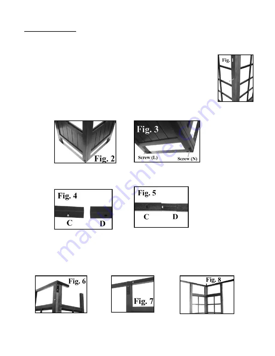
Stand the screen (A) at a right square angle to the screen (B). Attach them together by
inserting two screws M6*85 (N) at the top hole and middle hole, secure each screw in place with
nut (N) (Fig. 1). Do not insert screw to the bottom hole at this time as the screen binding (H) need
be attached to the bottom before fix screen bottoms; transpose assembly steps might result in
construction failure. Repeat this step for other three sets of screens (A & B).
Step 3.
Attach screen binding (H) to screens (A&B) bottoms, fix them by inserting one screw
M6*85 (N) and two screws M6*40 (L), secure screws (N&L) in place with nut (N&L) (Fig. 2 & Fig. 3). Repeat this step
for other three screen bindings (H).
Step 3.
Quick connect poles C and D,
make sure the snap links are locked into poles properly
(Fig. 4 & 5). Repeat
this step for remaining three sets of connecting poles (C&D) and assemble them into a whole rectangle frame.
Step 4.
Place the screens (A&B) upright and set them at four corners to form square approximately 10 feet across.
Set one connecting poles (D&C) above on screens (A&B), attach the corner connector that welded on connect pole
(C) to the screen (A) by inserting two screws M6*58 (M), secure them in place with nuts (M) (Fig. 6); then fix poles
(D&C) to other branches of screens (A&B) with screw & nut (L) (Fig.7). Repeat this step for other sets of connecting
poles (C&D). Your assembled poles (C&D) and screens (A&B) should look like figure 8.
Step 5.
Join top pole (E) to center fitting (F) by inserting E into F, make sure the snap links of center fitting (F) are
locked into top pole (F) (Fig. 9). Your top assembly should look like figure 10.


