background image

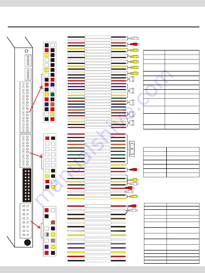
6. Pin Specification of Connector

Po

wer


LV

D

S-

OUT


AV


M

U

LT

U

SB


U

SB


M

IC


15 

16 

15 

16 

14 
11 

10 


AUDIO OUT(R) 

AUDIO OUT(L) 

AUDIO OUT GROUND 

AUX-ON 

CAN2-L 

CAN1-L 

REAR 

MMI 

CAN2-H 

CAN1-H 

SAFE 

ACC 

GROUND 

FRONT 

AUDIO OUT(R) 

AUDIO R Output 

AUDIO OUT(L) 

AUDIO L Output 

AUDIO OUT 

GROUND 

AUDIO Output GROUND 

AUX-ON 

Not available 

MMI 

Not available 

CAN2-L 

Connect with 

Car CAN2-Low 

CAN2-H 

Connect with  

CAN2-High 

CAN1-L 

Connect with  

Car CAN1-Low 

CAN1-H 

Connect with  

CAN1-High 

REAR 

Connect with Car Lame 

cable 

SAFE 

Not available 

FRONT 

Not available 

ACC 

Connect Car ACC 

GROUND 

Connect Car GROUND 

<Power Cable> 

<Multi Cable> 

31 

32 

AUDIO OUT (L) 
AUDIO OUT (L) 

VIDEO IN1 

FRONT-C 

VIDEO OUT1 


AUDIO OUT (R) 
AUDIO OUT (R) 

FRONT-C 

VIDEO OUT1 

QSOL 

VIDEO IN1 

REAR-C 

SPEAKER 

QSOL 

QSOL 

REAR-C 

VIDEO OUT2 

QSOL 

REAR 

IR-AV2 

VIDEO OUT2 

SPEAKER 

REAR 

IR-AV1 

TOGGLE 

QSOL 

QSOL 

TOGGLE 

GPS 
GPS 
GPS 
GPS 

AUDIO OUT(L) 

AUDIO L Input 

AUDIO OUT(R) 

AUDIO R Inut 

VIDEO IN1 

VIDEO Input1 

REAR-C 

Connect Rear Camera 

VIDEO 

FRONT-C 

Not available 

VIDEO OUT2 

VIDEO Output2 

VIDEO OUT1 

VIDEO Output1 

SPEAKER 

Connect with Speaker 

QSOL 

Not available 

REAR 

Connect Rear Camera 

IR-AV2 

Connect external 

device IR Cable 

IR-AV1 

Connect external 

device IR Cable 

TOGGLE 

Connect QDIS Button 

Cable (For switching 

mode) 

GPS 

Connect GPS Cable 

32 

31 

29 

26 

22 

30 

28 

25 

21 

17 

27 

24 

20 

16 

12 

23 

19 

15 

11 

18 

14 

10 

13 

<AV Cable> 

BT 
BT 
BT 
BT 
BT 
BT 

BT 

BT 

AUDIO IN3(R) 

VIDEO IN3 

AUDIO IN3(L) 

AUDIO IN2(L) 

VIDEO IN2 

BT 

BT 

AUDIO IN3(R) 

AUDIO IN3(L) 

VIDEO IN3 

AUDIO IN2(R) 

VIDEO IN2 

BT 

Not available 

AUDIO IN3(R) 

AUDIO R Input3 

AUDIO IN3(L) 

AUDIO L Input3 

VIDEO IN3 

VIDEO Input3 

AUDIO IN2(R) 

AUDIO R Input2 

AUDIO IN2(L) 

AUDIO L Input2 

VIDEO IN2 

VIDEO Input2 

19 

20 

CarNavi-Tech

Summary of Contents for Q-Roi

Page 1: ...better driving SUNE TECHNOLOGY CO LTD No 9 Lane 606 Anping Rd Tainan City 70849 TAIWAN TEL 88662292246 FAX 88662288104 Http www sune tech com Shop http www carnavi tech com SKYPE sune_tech or hsin_han99 C a r N a v i T e c h ...

Page 2: ...plete test all vehicle electrical systems to ensure they operate correctly including lights horn brake lights and emergency flashers According to our sales policy any problems caused by user s mistake careless can not be guaranteed Caution All steps of installation should be done by well trained specialist During installation ignition key should be taken off and after all installation finish conne...

Page 3: ...pec 2 System Diagram 3 Components 4 Setting up Dip S W 5 Installation diagram 6 Pin Specification of Connector Installation Diagram 7 Cautions before Installation 8 Installation 9 Quality Warranty C a r N a v i T e c h ...

Page 4: ... Input x 3 Rear Cam Input x 1 CAN Controller Area Network x 2 Mic x 1 External Speaker x 1 mono External Audio Out x 1 Car Aux Output LVDS thru Video Interface RGB thru Sub Board Touch Type Resistive Touch GPS SiRF Resolution 800 480 or 1024 480 USB USB 2 0 x 5 USB x 4 OTG USB x 1 Input Voltage 12V Temperature operating 0 C to 60 C Storage 20 C to 60 C Languages multi languages C a r N a v i T e c...

Page 5: ...sor With 2 CAN ports CAN Transceivr CAN Transceive USB HUB Audio Amp Touch Screen Controller LCD Display Rear Camera DVD Player Other Composite Video Signal Speakers Touch Screen Button CAN data Steering wheel CAN data USB Devices USB memory Hard Disc Wifi dongle BlueTooth dongle 3G LTE dongle Other USB Accessories Microphone C a r N a v i T e c h ...

Page 6: ...1ea HAVCAB0016 GPS Antenna 1ea GPSANT0006 Multi cable 1ea HARETC0068 Power cable 16P 1ea HPOWER0041 Microphone cable 1ea MICPHO0001 TOUCH cable 1ea HTOUCH0007 LVDS cable 1ea HALVDSC0020 3G dongle 1ea Option ETCETC0116 WIFI dongle 1ea Option ETCETC0110 Sub bard 1ea QCPASS0000 FFC cable 1ea FFCABL0000 Bolt 4ea Bolt 3ea C a r N a v i T e c h ...

Page 7: ... 7 No Use 8 Booting options ON Start with Q ROI OFF Start with OEM Please make sure to disconnect the power cable of the interface and reconnect the power cable again to apply the dip switch setting whenever changing DIP switch Otherwise DIP switch setting will not be applied ON DOWN OFF UP C a r N a v i T e c h ...

Page 8: ...CAM POWER cable GPS SPK Speaker REAR 12V OUT GND TOGGLE MIC Provided LVDS cable POWER cable ACC CAN1 H N C AUX GND A OUT R CAN2 H GND N C A OUT L CAN1 L CAN2 L FRONT SAFE REAR MMI AUX ON Monitor It will be Plug Play C a r N a v i T e c h ...

Page 9: ... QSOL REAR C VIDEO OUT2 QSOL REAR IR AV2 VIDEO OUT2 SPEAKER REAR IR AV1 TOGGLE QSOL QSOL TOGGLE GPS GPS GPS GPS AUDIO OUT L AUDIO L Input AUDIO OUT R AUDIO R Inut VIDEO IN1 VIDEO Input1 REAR C Connect Rear Camera VIDEO FRONT C Not available VIDEO OUT2 VIDEO Output2 VIDEO OUT1 VIDEO Output1 SPEAKER Connect with Speaker QSOL Not available REAR Connect Rear Camera IR AV2 Connect external device IR Ca...

Page 10: ...ithout manufacturer s permission can not be guaranteed No permission to break attached label on the board Kindly check all parts are in the box when receiving the product if anything missing inform to the supplier or manufacturer Install GPS away from electromagnetic devices such as black boxes Hi Pass and etc Advisable to Install GPS at the edge of dash board or a front window or a rear window In...

Page 11: ...8 Installation 8 Please dismantle a monitor and head unit as above C a r N a v i T e c h ...

Page 12: ... 9 Disconnect a FFC cable connected between a command and a monitor 8 Installation C a r N a v i T e c h ...

Page 13: ... 10 Take away the cover of the board 8 Installation C a r N a v i T e c h ...

Page 14: ... 11 Disconnect the OEM FFC from the connector 8 Installation Disconnect the OEM FFC from the connector C a r N a v i T e c h ...

Page 15: ... 12 8 Installation Connect supplied FFC cable to connectors where OEM FFC were connected Supplied FFC cable Supplied FFC cable C a r N a v i T e c h ...

Page 16: ... 12 Please screw 3 numbers of supports as above 8 Installation C a r N a v i T e c h ...

Page 17: ... 12 Please connect FFC cables as above 8 Installation OEM Supplied FFC C a r N a v i T e c h ...

Page 18: ...01 CN102 pass through the supplied board Please connect the original FFC cable CN102 to LCD out Please connect OEM FFC to touch in and supplied cables to touch out FFC cables pass through pointed spaces 8 Installation C a r N a v i T e c h ...

Page 19: ... 12 Please connect FFC cables 8 Installation Supplied FFC cable OEM OEM C a r N a v i T e c h ...

Page 20: ... 12 Please do not put the cover of the board 8 Installation Please screw bolts Remove the cover C a r N a v i T e c h ...

Page 21: ... 12 Please dismantle head unit as above 8 Installation C a r N a v i T e c h ...

Page 22: ... 12 Please dismantle a Fan as above Pass through the supplied LVDS cable on the top left of Fan Reassemble the unit 8 Installation C a r N a v i T e c h ...

Page 23: ... 12 After reassembling the unit 8 Installation C a r N a v i T e c h ...

Page 24: ... 12 Connect FFC cables and LVDS cable 8 Installation C a r N a v i T e c h ...

Page 25: ...responsible to repair free of charge Please bring this warranty to dealer whom you purchased this product from at the repair time Should this warranty not presented repair charged will be on customer Please keep this warranty card Warranty Product name Warranty period 1 year Purchase date yy mm dd Customer Address TEL Name Dealer Address Name 9 Quality Warranty C a r N a v i T e c h ...

Reviews: