background image

88

Netra t1 User and Administration Guide • June 2000

The Fans Monitored by the LOM Device

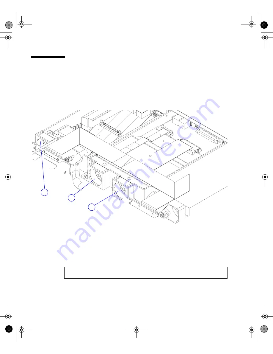
Event reports about the fans inside the system include the number of the fan to
which they relate. Fans 1 and 2 cool the motherboard (see

FIGURE 9-5

), and Fan 3

cools the PCI bay. The power supply fan is monitored as part of the Power Supply
Unit (PSU), therefore, if this fan fails, the LOM reports it as a PSU failure.

FIGURE 9-5

Locations of Fans 1, 2, and 3

To check the status of the fans:

1. Type the LOM escape sequence (by default this is #.) to get to the

lom>

prompt.

2. Type the following at the

lom>

prompt:

lom> environment

3

2

1

SysAdmin.book  Page 88  Friday, March 30, 2001  2:38 PM

Summary of Contents for Netra t1 100

Page 1: ...nio Road Palo Alto CA 94303 U S A 650 960 1300 Send comments about this document to docfeedback sun com Netra t1 User and Administration Guide Part No 806 4707 10 June 2000 Revision A SysAdmin book Pa...

Page 2: ...nc 901 San Antonio Road Palo Alto CA 94303 Etats Unis Tous droits r serv s Ce produit ou document est prot g par un copyright et distribu avec des licences qui en restreignent l utilisation la copie l...

Page 3: ...e of Different Environmental Conditions 4 Acoustic Noise Generated by the Netra t1 5 Environmental Compliance Information 5 Choosing Between a Rack and a Cabinet 5 2 Operating Power and Cooling 7 Oper...

Page 4: ...6 Installing a CD ROM Drive 27 Installing Additional Memory 29 Installing a PCI Card 29 5 Installing the Netra t1 into a Rack 31 Installing into a Sun 72 inch Rack 32 The 72 inch Expansion Rack Mounti...

Page 5: ...m a Terminal or Workstation 60 To Power the System Up for the First Time 61 Using the Power On Standby Switch 63 8 Using Different Versions of Solaris 65 Installing Solaris release 2 6 66 To Install S...

Page 6: ...the Current Status of all Components Monitored by the LOM 80 Viewing the LOM Device s Event Log 81 Shortening the LOM Commands 82 A Listing of the LOM commands 82 Configuring the LOM to Restart the Sy...

Page 7: ...equired 102 To Install a Second Memory Board 103 Installing 4 x 256 Mbyte Memory Boards 107 Materials and Tools Required 107 To Install a Stack of Four Memory Boards 109 B Installing a PCI Card 117 To...

Page 8: ...viii Netra t1 User and Administration Guide June 2000 SysAdmin book Page viii Friday March 30 2001 2 38 PM...

Page 9: ...Relief Housing 20 FIGURE 4 1 Inserting Hard Disks into the Drive Bays 22 FIGURE 4 2 Using an Anti Static Wrist Strap 23 FIGURE 4 3 Removing the Rack Mount Brackets 24 FIGURE 4 4 Removing the Top Cove...

Page 10: ...ystem 48 FIGURE 6 3 Model 100 Connecting a DC Power Cord 50 FIGURE 6 4 Model 105 Connecting the AC Power Cord 50 FIGURE 6 5 Patch Panel Connection Between a Cisco L2511 and a Netra t1 System 53 FIGURE...

Page 11: ...cers with the Mounting Holes 112 FIGURE A 12 Mounting the Second and Third Boards onto the Base Memory Board 113 FIGURE A 13 Four Stacked Memory Boards on the Netra t1 Motherboard 114 FIGURE A 14 Drop...

Page 12: ...xii Netra t1 User and Administration Guide June 2000 SysAdmin book Page xii Friday March 30 2001 2 38 PM...

Page 13: ...3 Fixed Bracket Mounting Kit 43 TABLE 6 1 Pin Cross overs for Connecting to a Typical Terminal Server 54 TABLE 6 2 Pin Cross overs in the Sun DB25 25 pin Adapter 55 TABLE 6 3 Pin Cross overs for a DB9...

Page 14: ...xiv Netra t1 User and Administration Guide June 2000 SysAdmin book Page xiv Friday March 30 2001 2 38 PM...

Page 15: ...uirements for the Netra t1 Chapter 3 Using DC Power Tells you the site requirements for using DC power and also tells you how to assemble the DC input power cable Chapter 4 Installing Hardware Option...

Page 16: ...r for the Netra t1 during its life time If you ever need to replace an entire Netra t1 system the chapter also tells you how to retain the configuration information for one system so that it can be tr...

Page 17: ...mputer output su Password AaBbCc123 Book titles new words or terms words to be emphasized Command line variable replace with a real name or value Read Chapter 6 in the User s Guide These are called cl...

Page 18: ...uipment Follow all cautions and instructions marked on the equipment Never push objects of any kind through openings in the equipment Dangerous voltages may be present Conductive foreign objects can p...

Page 19: ...re does not exceed 40 degrees The system will tolerate ambient temperatures of up to 55 degrees but these temperatures must not persist for more than 96 hours Caution Mounting of the equipment in a ra...

Page 20: ...xx Netra t1 User and Administration Guide June 2000 SysAdmin book Page xx Friday March 30 2001 2 38 PM...

Page 21: ...PART I Installation and Configuration SysAdmin book Page 1 Friday March 30 2001 2 38 PM...

Page 22: ...SysAdmin book Page 2 Friday March 30 2001 2 38 PM...

Page 23: ...Modules Available on page 3 The Tools You Need for Installation on page 4 Your Operating Environment on page 4 Choosing Between a Rack and a Cabinet on page 5 What s Next When you have read this chapt...

Page 24: ...ocessor with 2 Mbyte cache Sockets accepting 64 256 and 512 Mbyte memory cards in single board 2 stack or 4 stack configurations giving a maximum of 1 Gbyte of memory One short 176 mm 33 MHz 32 bit 5V...

Page 25: ...k mounting brackets 4 340 6151 01 Cable management bracket 1 540 4362 01 Sun slide rail 2 530 2093 01 RJ45 RJ45 patch cable for Ethernet or serial connection 2 530 2889 02 RJ45 DB25 adapter 1 565 1644...

Page 26: ...ed these tools if you need to use a two hole ground connection see Chapter 3 Your Operating Environment The System s Tolerance of Different Environmental Conditions You can operate and store the syste...

Page 27: ...et Netra t1 servers can be installed in either racks or cabinets Factors that may influence your decision include Security If other people have access to the room in which your Netra systems are locat...

Page 28: ...6 Netra t1 User and Administration Guide June 2000 SysAdmin book Page 6 Friday March 30 2001 2 38 PM...

Page 29: ...ge 10 What s Next When you have used this chapter to calculate the power and cooling requirements for your Netra t1 system go to Chapter 3 which tells you how to assemble the DC input power cables for...

Page 30: ...Logic ground and chassis ground are connected together internally within the system Note Power from the standby output is available whenever input power is connected TABLE 2 1 Operating Power Statisti...

Page 31: ...d the figures from the third column of TABLE 2 2 for each component installed in the system Then divide the result by 0 65 Below are two examples Example A The power requirement for a Netra t1 system...

Page 32: ...gure for the system s power requirement see Calculating the Power Requirements for your Netra t1 on page 9 from watts to BTU hr A general formula for doing this is to multiply the figure for the power...

Page 33: ...DC Connection Materials on page 14 Assembling the DC Input Power Cable on page 15 What s Next When you have followed the instructions in this chapter to assemble the DC input power cables go to Chapt...

Page 34: ...r reinforced insulation from any hazardous AC or DC source Reliably connected to earth Capable of providing up to 150 W of continuous power per feed pair Note The Netra t1 Model 100 must be installed...

Page 35: ...lectrical safety codes and be approved for the intended application TABLE 3 1 Overcurrent Protection Requirements Description Requirement Current rating 7 5A maximum Voltage Maximum 60 VDC rated in 48...

Page 36: ...suppression devices may be required on the power feeds where branch circuit electromagnetic characteristics are unknown DC Supply and Ground Conductor The requirements are Suitable conductor material...

Page 37: ...tion to your unit 48V Supply Chassis ground 48V Return 5 Strip 8mm 0 31 inches of insulation from each of the wires coming from the DC power source see FIGURE 3 1 Do not strip more than 8mm 0 31 inche...

Page 38: ...u can also open the DC connector cage clamp by inserting a small slotted screwdriver into the rectangular hole directly above the hole in the DC connector where you want to insert the first wire and p...

Page 39: ...wer Cable 8 Repeat Step 6 and Step 7 for the other two wires to complete the assembly of the DC input power cable 9 Repeat Step 4 through Step 8 to create as many DC input power cables as you need If...

Page 40: ...sure the strain relief housing snaps into place on the DC connector you will not be able to complete the assembly correctly if the strain relief housing is not snapped into place FIGURE 3 5 Inserting...

Page 41: ...ottom portion of the strain relief housing see FIGURE 3 7 FIGURE 3 7 Securing the Wires to the Strain Relief Housing 4 Loop the tie wrap over the wires and back out of the strain relief housing and ti...

Page 42: ...snap into place see FIGURE 3 8 FIGURE 3 8 Assembling the Strain Relief Housing What s Next The DC input power cables for your unit are now completely assembled For information about connecting the pow...

Page 43: ...ystem and how to install a CD ROM drive For the sales part numbers of the Netra t1 hardware option modules available from your Sun Enterprise Services representative see Chapter 10 The chapter contain...

Page 44: ...FIGURE 4 1 Inserting Hard Disks into the Drive Bays 2 Lever out the grilles 3 If you are Installing hard disk drives slide the disk drive s into their trays in the front of the system see FIGURE 4 1 P...

Page 45: ...are extremely sensitive to static electricity Do not touch any metal parts Wear an anti static wrist strap connected to an earthing point before you open the system FIGURE 4 2 Using an Anti Static Wri...

Page 46: ...switch off c Disconnect the power cord s d Disconnect all other cables 2 If you have installed the system into a rack or cabinet remove it 3 Remove the rack mount brackets from the side of the system...

Page 47: ...Chapter 4 Installing Hardware Option Modules 25 FIGURE 4 4 Removing the Top Cover 1 2 2 3 5b 5a SysAdmin book Page 25 Friday March 30 2001 2 38 PM...

Page 48: ...12 14 13 Key to FIGURE 4 1 1 Processor cover 2 PCI card 3 Mid baffle 4 CD ROM drive board and cable 5 Cover 6 Hard disk drive 7 CD ROM drive replaces 8 8 Blanking plate replaces 7 9 Front bezel 10 Gri...

Page 49: ...not attempt to install a CD ROM drive using any procedure other than the one contained in this section If you do you risk exposure to radiation FIGURE 4 6 Installing an Internal CD ROM Drive Class 1 L...

Page 50: ...the latch at each end see FIGURE 4 6 3 Remove any PCI card installed in the system see Appendix B 4 Squeeze and pull out the blanking panel 5 Slide the connector card into the slot behind the CD ROM...

Page 51: ...rds available from your Sun Enterprise Services representative see Chapter 10 To install new memory boards follow the instructions in Appendix A Installing a PCI Card For a list of the Ethernet Fast E...

Page 52: ...30 Netra t1 User and Administration Guide June 2000 SysAdmin book Page 30 Friday March 30 2001 2 38 PM...

Page 53: ...Installing into a Sun 72 inch Rack on page 32 Installing into a 19 inch Rack on page 38 Installing into a Two Post Relay Rack on page 43 What s Next When you have installed the Netra t1 system into t...

Page 54: ...required are listed below A bracket is provided to aid cable management at the rear of the system see FIGURE 5 1 FIGURE 5 1 Cable Management Bracket TABLE 5 1 72 inch Expansion Rack Mounting Kit Descr...

Page 55: ...he two parts together using the M4 nuts supplied see FIGURE 5 2 FIGURE 5 2 Slide Mounts for Sun 72 inch Expansion Rack 3 Adjust the mount to fit the rack 4 Move the brackets so that the studs are in s...

Page 56: ...tra t1 User and Administration Guide June 2000 FIGURE 5 3 Fixing Slide Mounts into a Sun 72 inch Expansion Rack Rear View side panels removed for clarity SysAdmin book Page 34 Friday March 30 2001 2 3...

Page 57: ...er 5 Installing the Netra t1 into a Rack 35 FIGURE 5 4 Fixing Slide Mounts into the Sun 72 inch Expansion Rack Front View side panels removed for clarity SysAdmin book Page 35 Friday March 30 2001 2 3...

Page 58: ...etra t1 system see FIGURE 5 5 FIGURE 5 5 Adjusting the Mount and Tightening the Thumbscrew 8 Fasten the slide mount fixing screws It may be necessary to readjust the fixings in order to align the syst...

Page 59: ...the bracket to secure the cables with cable ties FIGURE 5 6 The Cable Management Bracket Installed in a Sun 72 inch Expansion Rack What s Next When you have installed the Netra t1 system into the rac...

Page 60: ...ired are listed below A bracket is provided to aid cable management at the rear of the system see FIGURE 5 7 FIGURE 5 7 The Cable Management Bracket TABLE 5 2 19 inch Rack Mounting Kit Description Qua...

Page 61: ...rs are the correct distance apart then loosely secure the two parts together using the M4 nuts supplied 3 Adjust the mount to fit the rack The ears must be outside the rack 4 Move the brackets so that...

Page 62: ...he alignment of the thumbscrews either side of the Netra t1 system see FIGURE 5 10 8 Fasten the slide mount fixing screws see FIGURE 5 10 It may be necessary to readjust the fixings in order to align...

Page 63: ...Chapter 5 Installing the Netra t1 into a Rack 41 FIGURE 5 10 Fitting the Netra t1 into a 19 inch Rack SysAdmin book Page 41 Friday March 30 2001 2 38 PM...

Page 64: ...loops in the bracket to secure the cables with cable ties FIGURE 5 11 The Cable Management Bracket Installed in a 19 inch Rack What s Next When you have installed the Netra t1 system into the rack go...

Page 65: ...To Fit the Fixed Mounting Brackets 1 Remove the thumbscrew rack mounting brackets from either side of the system see FIGURE 5 12 FIGURE 5 12 Removing the Thumbscrew Brackets TABLE 5 3 Fixed Bracket M...

Page 66: ...tting the Fixed Mounting Brackets 3 Now secure the system to the rack using just the front brackets but do not fully tighten the screws yet 4 Fit the two rear fixed brackets to the two tapped holes at...

Page 67: ...Chapter 5 Installing the Netra t1 into a Rack 45 FIGURE 5 14 The Netra t1 Installed in a Two Post Rack SysAdmin book Page 45 Friday March 30 2001 2 38 PM...

Page 68: ...Guide June 2000 What s Next When you have installed the Netra t1 system into the rack go to Chapter 6 for information about connecting up the cables and setting up serial connections SysAdmin book Pa...

Page 69: ...ing the instructions in this chapter The chapter contains the following sections Connecting the Cables to the Netra t1 on page 48 Connecting the Power Cord s on page 50 Setting up Serial Connections o...

Page 70: ...tration Guide June 2000 Connecting the Cables to the Netra t1 FIGURE 6 1 Connecting the Netra t1 Model 100 System FIGURE 6 2 Connecting the Netra t1 Model 105 System 1 2 3 4 5 6 SysAdmin book Page 48...

Page 71: ...nt see Chapter 9 4 If you intend to configure the Netra t1 system directly from a dumb terminal or a Sun workstation insert the serial cable into the DB25 adapter supplied see FIGURE 6 1 and FIGURE 6...

Page 72: ...contains diagrams showing how the DC connectors for the Model 100 and the AC connector for the Model 105 connect to the system FIGURE 6 3 Model 100 Connecting a DC Power Cord FIGURE 6 4 Model 105 Con...

Page 73: ...ug Sun products into any other type of power system Contact your facilities manager or a qualified electrician if you are not sure what type of power is supplied to your building Caution Your AC power...

Page 74: ...to a Terminal Server The pinouts for the Netra t1 system s serial ports correspond with the pinouts for the RJ45 ports on the Asynchronous Serial Interface Breakout Cable supplied by Cisco for use wit...

Page 75: ...u are using a Cisco L2511 Terminal Server and you are connecting the Netra t1 system to it using the Cisco Asynchronous Serial Interface Breakout Cable you can either connect the Breakout Cable direct...

Page 76: ...o 8 TABLE 6 1 Pin Cross overs for Connecting to a Typical Terminal Server Netra t1 Serial Port RJ45 Connector Pin Terminal Server Serial Port Pin Pin 1 RTS Pin 1 CTS Pin 2 DTR Pin 2 DSR Pin 3 TXD Pin...

Page 77: ...sted in TABLE 6 2 Note If you need to set up a modem connection to the Netra t1 system you must use the port labeled Serial B The Serial A LOM port does not assert the required constant DTR signal Not...

Page 78: ...m the rear of the Netra t1 system pin 1 of the RJ45 serial port is on the left pin 8 on the right FIGURE 6 8 Pins 1 to 8 on the Serial Ports TABLE 6 3 Pin Cross overs for a DB9 9 pin Adapter Serial Po...

Page 79: ...bject to interruption by the Lights Out Management LOM device see Chapter 9 What s Next When you have connected up the cables and set up serial connections to the Netra t1 you are ready to power up th...

Page 80: ...58 Netra t1 User and Administration Guide June 2000 SysAdmin book Page 58 Friday March 30 2001 2 38 PM...

Page 81: ...andby Switch on page 63 What s Next When you have followed the instructions in this chapter telling you how to power on the system and when you have booted and logged in go to Chapter 8 for informatio...

Page 82: ...minal Server whose IP address is 192 20 30 10 you would type Configuring from a Terminal or Workstation To access the Netra t1 system from a dumb terminal just set up a connection between the terminal...

Page 83: ...commands that are available from it see Chapter 9 2 During booting you will be prompted for certain information The first question the system asks you is what language you want it to use when it prom...

Page 84: ...ation the system needs 16 When prompted give a password if any for users logging in as root 17 When asked if you want the sytem to perform Automatic Power Saving Shutdown answer No Note If you answer...

Page 85: ...g or disconnecting power is by inserting or removing the power supply cord s The system contains no integral circuit breakers To isolate it you must break all connections to it If you do not do this b...

Page 86: ...64 Netra t1 User and Administration Guide June 2000 SysAdmin book Page 64 Friday March 30 2001 2 38 PM...

Page 87: ...ion supplied with Solaris 7 and Solaris 8 if you need to install either of those operating systems yourself for example if you install Solaris 2 6 but then decide to upgrade to Solaris 7 or 8 The Sola...

Page 88: ...is 2 6 5 98 CDs part no 704 6220 10 Solaris Operating Environment Installation CD 9 99 This CD is supplied with the Netra t1 part no 704 6914 10 It includes the kernel update patch 105181 xx you need...

Page 89: ...2 6 5 98 CD onto the local disk of the system you are using as the net install server 2 When the install server setup is complete remove the Solaris 2 6 5 98 CD and insert the Solaris Operating Enviro...

Page 90: ...you are installing Solaris 7 we recommend you install the version dated 11 99 or later Note The Netra t1 s factory installed software includes the Lights Out Management software If you install a new o...

Page 91: ...an external CD ROM drive in a Netra t1 system that does not contain an internal CD ROM drive type If you are booting from an external CD ROM drive and your Netra t1 system also contains an internal CD...

Page 92: ...ootTM PROM OBP software specifically for the Netra t1 It is required because the default parameter settings in versions of the OBP software used on other Sun platforms are not correct for the Netra t1...

Page 93: ...nds Note Whenever you use the set defaults command from the ok prompt make sure you afterwards set the variables listed in Step 2 above ok setenv pcib probe list 1 2 3 ok setenv output device ttya ok...

Page 94: ...72 Netra t1 User and Administration Guide June 2000 SysAdmin book Page 72 Friday March 30 2001 2 38 PM...

Page 95: ...PART II Maintenance and Management SysAdmin book Page 73 Friday March 30 2001 2 38 PM...

Page 96: ...SysAdmin book Page 74 Friday March 30 2001 2 38 PM...

Page 97: ...OM Device Sends its Event Reports on page 77 Interrogating the LOM and Using it to Power Up or Reset the System on page 79 Configuring the LOM to Restart the System Automatically After a Lock up on pa...

Page 98: ...ware that is pre installed on your system during manufacturing Note If you install new system software onto the Netra t1 and you want to continue using the Lights Out Management facility you must re i...

Page 99: ...re from a CD part number X6972A that is available from your Sun Enterprise Services representative When the Operating System is Running and the lomlited Daemon is Installed and Running When the operat...

Page 100: ...A Port When the Daemon is not Running on page 78 Capturing LOM Event Reports Passively on the Serial A LOM Port To monitor LOM events as they occur keep a terminal connected to Serial Port A For info...

Page 101: ...serial connections to the Netra t1 see Chapter 6 To use the LOM commands type the LOM escape sequence at a console connected to the Serial A LOM port The escape sequence is hash period When you type...

Page 102: ...Fault LED is ON because Fan 3 is running too slowly All the Alarms are OFF Fan 3 is faulty and one of the DC inputs in this case input A to the Power Supply Unit has failed FIGURE 9 1 The environment...

Page 103: ...ommand the reset command The only fatal error is the fan 3 failure No other fatal errors have occurred The PSU In A failure is not fatal because it affects a component the input supply that is externa...

Page 104: ...off command For the minimum abbreviation permissible for each command see TABLE 9 1 A Listing of the LOM commands The LOM commands are listed in TABLE 9 1 lom re TABLE 9 1 LOM Commands Command Minimum...

Page 105: ...m show model sh mo Displays the system model show hostname sh ho Displays the system name this command is equivalent to the UNIX uname n command show eventlog sh ev Displays the LOM s event log The ev...

Page 106: ...n event and lights the Fault LED but it does not by default reset the system To make the LOM device reset the system when its watchdog timer has timed out after not receiving a pat from the tsdog watc...

Page 107: ...Boolean Causes the LOM to reset the Netra t1 after a tsdog watchdog timeout wdog_alarm3 Boolean Turns on software alarm 3 when the tsdog watchdog times out wdog_timeout Integer Sets the timeout for th...

Page 108: ...evice They are stored in usr sbin For information about using these to perform more advance monitoring and configuration refer to the manpages for lomctl 1M lominfo 1M lomprog 1M lom 1M tsdog 1M tssta...

Page 109: ...hing then the LOM has detected a fault that requires you to take action for example to replace a fan or power supply unit that has failed You can use the LOM s faulton command to light this LED yourse...

Page 110: ...URE 9 5 and Fan 3 cools the PCI bay The power supply fan is monitored as part of the Power Supply Unit PSU therefore if this fan fails the LOM reports it as a PSU failure FIGURE 9 5 Locations of Fans...

Page 111: ...uration information is stored in a device on the motherboard called the Host ID chip The chapter also tells you how to identify the part that needs replacing if you see a message during booting which...

Page 112: ...kit X6971A Internal CD ROM drive X6971A External SCSI CD ROM drive X6157A Lights out Management software CD X6972A 9 Gbyte 7 2K RPM hard disk X5229A 9 Gbyte 10K RPM hard disk X5234A 18 Gbyte 10K RPM...

Page 113: ...omponent called the Host ID chip see FIGURE 10 1 To transfer them to a new system do the following 1 Remove the Host ID chips from both the new and the old systems to identify the chip see FIGURE 10 1...

Page 114: ...Replace it only with a battery of the same type as the used battery part number 100 5893 or with a battery of an equivalent type that has been recommended by Sun Microsystems Inc To replace the batte...

Page 115: ...No jumper provided J1502 2 3 Scan Clock 1 2 External Clock Installed J3301 2 3 Enable Loopback Reset Installed 1 2 Disable Loopback Reset J3302 2 3 Enable User Flash Write Installed 1 2 Disable User F...

Page 116: ...s J1501 o JTAG test header Do not install jumpers or shunt here Mechanical stabilizer for the I2C board J3304 J1502 J4703 J1001 J3302 J1401 J1002 J3401 J3601 J3602 J3306 Memory module mezzanine board...

Page 117: ...ive The chapter contains information to help you when you Cannot Set up a Console Connection to the Netra t1 on page 96 Cannot Boot from the Internal CD ROM drive on page 96 Cannot Plug the Network Ca...

Page 118: ...applied but you have no operating system installed do the following 1 At the ok prompt type 2 Next type 3 If you had the auto boot environment variable set to true originally return it to true by typi...

Page 119: ...was pre installed on your Netra t1 system you must re install the LOM software from an orderable CD part number X6972A Cannot Install Solaris from the Solaris 2 6 hw3 CD To install Solaris 2 6 on to t...

Page 120: ...000 Patch 106533 xx creates new device nodes dev term a and dev term b for the Netra t1 s serial ports When you boot with the r option these new device nodes are included in the rebuilt device tree Sy...

Page 121: ...PART III Appendices SysAdmin book Page 99 Friday March 30 2001 2 38 PM...

Page 122: ...SysAdmin book Page 100 Friday March 30 2001 2 38 PM...

Page 123: ...stacks of three These boards can only be installed singly or in stacks of two or four Only boards of part number 370 4155 can be installed in stacks of four see Installing 4 x 256 Mbyte Memory Boards...

Page 124: ...e for purchase 512 Mbyte memory board part number 595 5316 sales part number X6986A Note Do not install memory boards in a stack of three These boards can only be installed singly or in twos The 256 M...

Page 125: ...n Failure to comply may result in damage to the equipment 1 Remove the Netra t1 system cover see Opening the Netra t1 System on page 23 in Chapter 4 2 Lift out the processor cover located in the rear...

Page 126: ...ew spacers over the screw holes see FIGURE A 4 6 Insert the new longer screws with their washers through the holes in the new board see FIGURE A 4 Place the spring washer on the screws first and then...

Page 127: ...three memory board connectors until they are firmly seated in the connectors on the board beneath see FIGURE A 5 You might find it helpful to seat the middle connector properly before the other two c...

Page 128: ...tures on the motherboard which can impair the operation of the board 10 Tighten the securing screws so that the boards sit firmly on the motherboard The recommended tightening torque is 0 3 Nm 11 Repl...

Page 129: ...n stacks of three If you do not want to install four boards into a system you can install the boards either singly or in twos Materials and Tools Required The packaging containing your 4 stackable 256...

Page 130: ...ry board kits To order a single kit from your Sun Enterprise Services representative quote the sales part number X6985A 4 square spacers Label 4 stack ONLY 4 long screws 11 16 inch Memory board 4 lock...

Page 131: ...System on page 23 in Chapter 4 2 Lift out the processor cover located in the rear center of the unit see FIGURE A 7 Make sure you slide the processor cover tabs from under the rear I O card before lif...

Page 132: ...as the base board will be called Board A Board B will be the board you put on top of Board A Board C will be the one you put on top of Board B and Board D will be the one at the top of the stack FIGU...

Page 133: ...on of the board 5 Position the connectors of one memory board Board C above the memory board connector sockets of another memory board Board B in a piggy back style then press down the connectors usin...

Page 134: ...ard on Top of the Second 6 Insert the four plastic spacers and align them with the mounting holes on memory Boards B and C see FIGURE A 11 FIGURE A 11 Aligning the Four Plastic Spacers with the Mounti...

Page 135: ...embled Boards B and C with spacers inserted onto memory Board A Hold the spacers if necessary so that they do not move out of position FIGURE A 12 Mounting the Second and Third Boards onto the Base Me...

Page 136: ...oards on the Netra t1 Motherboard 9 Insert each screw into one lock washer and one flat washer then drop the screws with the washers into the aligned mounting holes of the memory boards and the plasti...

Page 137: ...he connectors of Board D You might find it helpful to seat the middle connector properly before the other two connectors 12 Tighten the screws into the metal hex standoffs so that the stack sits firml...

Page 138: ...116 Netra t1 User and Administration Guide June 2000 SysAdmin book Page 116 Friday March 30 2001 2 38 PM...

Page 139: ...ns the following sections To Prepare the System for Installation on page 118 To Install the Card on page 121 Caution The components on the motherboard and PCI cards are extremely sensitive to static e...

Page 140: ...e you will have to remove the PCI card again 1 Remove the Netra t1 system cover see Opening the Netra t1 System on page 23 in Chapter 4 2 Lift out the processor cover located in the rear center of the...

Page 141: ...B 2 FIGURE B 2 Unclipping the Slide Retainer 4 Remove the mid baffle To do this a Remove the screw at the rear of the unit and push the mid baffle towards the drive bays see FIGURE B 2 FIGURE 11 1 Rem...

Page 142: ...the mid baffle out of the unit see FIGURE B 3 FIGURE B 3 Lifting Out the Mid Baffle 5 Remove the blanking panel or the PCI card currently occupying the PCI slot see FIGURE B 4 FIGURE B 4 Removing a P...

Page 143: ...d into the PCI connector so that it remains in a horizontal plane see FIGURE B 5 otherwise you might have difficulty accessing the PCI card s ports FIGURE B 5 Installing a PCI Card viewed from the fro...

Page 144: ...Administration Guide June 2000 2 Replace the mid baffle with the slide retainer attached see FIGURE B 6 Secure it with the rear screw FIGURE B 6 Replacing the Mid Baffle SysAdmin book Page 122 Friday...

Page 145: ...Push the slide retainer forward to hold the corner of the PCI card in place see FIGURE B 7 FIGURE B 7 Using the Slide Retainer to Hold the Corner of the PCI Card in Place Slide retainer SysAdmin book...

Page 146: ...corner tabs are put back underneath the rear I O card FIGURE B 8 Replacing the Processor Cover 5 Make another visual inspection of the installation to check that the horizontal alignment of the PCI c...

Page 147: ...he screw at the rear of the unit see FIGURE B 9 FIGURE B 9 Replacing the Lid 7 Re install the rack mount brackets if you removed them initially see FIGURE B 10 FIGURE B 10 Re installing the Rack Mount...

Page 148: ...126 Netra t1 User and Administration Guide June 2000 SysAdmin book Page 126 Friday March 30 2001 2 38 PM...

Page 149: ...6 installing 27 to 28 ordering 90 circuit breaker requirements 13 Cisco L2511 Terminal Server connecting 52 components 26 configuration 60 connecting the cables 48 contact gap 13 cooling heat dissipat...

Page 150: ...9 inch rack 38 additional memory 101 to 115 four 256 Mbyte memory boards 107 to 115 PCI card 117 to 125 rack mounting 31 second memory board 102 to 106 Sun 72 inch rack 32 tools required 4 two post re...

Page 151: ...3 110 112 to 114 installing four 256 Mbyte boards 107 to 115 memory module connectors 92 option boards 90 option boards available 29 mid baffle 26 removing 119 modem connection 52 to 53 55 interruptio...

Page 152: ...Lights Out Management LOM remote reset 80 removal hard disk drives 22 mid baffle 119 processor cover 109 118 rack mount brackets 24 system top cover 24 resetting remotely 80 restart after lock up 84...

Page 153: ...y rack 43 U UltraSCSI port 2 UltraSPARC II processor 2 V voltage frequency range 8 input range 8 protection requirements 13 volt ampere rating 8 W watchdog timeouts 85 wrist strap 23 X X options 90 Sy...

Page 154: ...132 Netra t1 User and Administration Guide June 2000 SysAdmin book Page 132 Friday March 30 2001 2 38 PM...

Reviews: