


Maintenance
39
Used Adsorber Venting and Disposal
For safe disposal of the used adsorber:
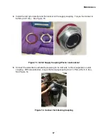
1.
A venting adapter fitting is included with the new adsorber. Attach it to one of the self-
sealing couplings on the
used
adsorber. Vent the
used
adsorber to atmospheric pressure.
2.
Discard the used adsorber with the venting adapter fitting connected.
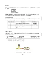
Charging or Venting
Tools required: Charge and vent tool with valve, #4Fx¼” Swagelok, P/N 267191A.
Bleed adapter, P/N 267192A
Open-end wrenches, 5/8", 3/4"
Helium gas cylinder with pressure regulator and charge line
Charging or venting is required whenever the equalization pressure of the system is outside the
range as stated in the Specifications. See the Specifications section of this manual. Venting a
component to atmospheric pressure is required if the component needs to be disassembled for
repairs or maintenance, including repairs to its self-sealing couplings.
AVOID INJURY.
Never use compressed helium gas from a cylinder without a
proper regulator. Overpressure can cause serious injury if the system
equipment ruptures.
AVOID CONTAMINATION.
Follow the charging and venting procedure to
prevent reversed flow of system gas. Do not charge through the supply
coupling. Do not vent through the return coupling. Reversed flow can
contaminate the system with compressor oil.
NOTE
Adapter fittings for charging and venting are available as optional service tools.
See the Parts section of this manual.
Charging Procedure
PRESERVE YOUR WARRANTY.
Specifications require the use of 99.999%
pure helium gas. Using a lesser quality of helium can damage the system and
void the warranty.
AVOID A MALFUNCTION.
Repeatedly charging the system with helium gas
rather than locating and repairing gas leaks can cause a malfunction. Impurities
are introduced at an abnormal rate and can freeze in the cold head.
Summary of Contents for F-20L
Page 2: ......
Page 10: ...6 This page is intentionally blank...
Page 12: ...8 This page is intentionally blank...
Page 23: ...Specifications 19 Figure 2 F 20L Compressor Front View...
Page 24: ...Specifications 20 Figure 3 F 20L Compressor Dimensions Dimensions are in inches and mm...
Page 34: ...30 This page is intentionally blank...
Page 36: ...32 This page is intentionally blank...
Page 48: ...44 This page is intentionally blank...
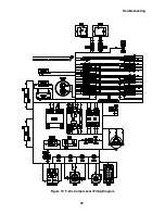
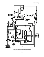
Page 53: ...Troubleshooting 49 Figure 19 F 20L Compressor Wiring Diagram...
Page 54: ...Troubleshooting 50 Figure 20 F 20L Compressor Wiring Schematic...