Sumitomo Drive Technologies PARAMAX SFC Operating Manual Download Page 8

PARAMAX SFC Operating Manual

e-mail: [email protected]
www.sumitomodriveeurope.com

Tel. +49 (0) 8136 66 0

Cyclostraße 92
85229 Markt Indersdorf

29

PX_SFC_DEU_ENG_11_09_991131

The drive unit is to be set up so that inspection, maintenance, and other operations such as lubricant 
top-ups, can be carried out easily. 

In order to prevent overheating and risk of fire, ventilation of the PARAMAX SFC gearbox should not be 
obstructed.

Tighten the mounting bolts to the specified torque only after carefully establishing perfect evenness 
over the entire surface of the mounting base, which should provide torsional stiffness and vibration 
damping, and after aligning the drive. After about 4 weeks, all mounting bolts should be checked again 
to ensure the correct tightening torque.
We recommend using mounting bolts of DIN quality 10.9.

If the drive is to be loaded up to maximum output torque or maximum transverse force, positive-fit con-
nections (e.g. DIN 6325 cylinder pins) should be provided in addition to the foot mounting bolts.
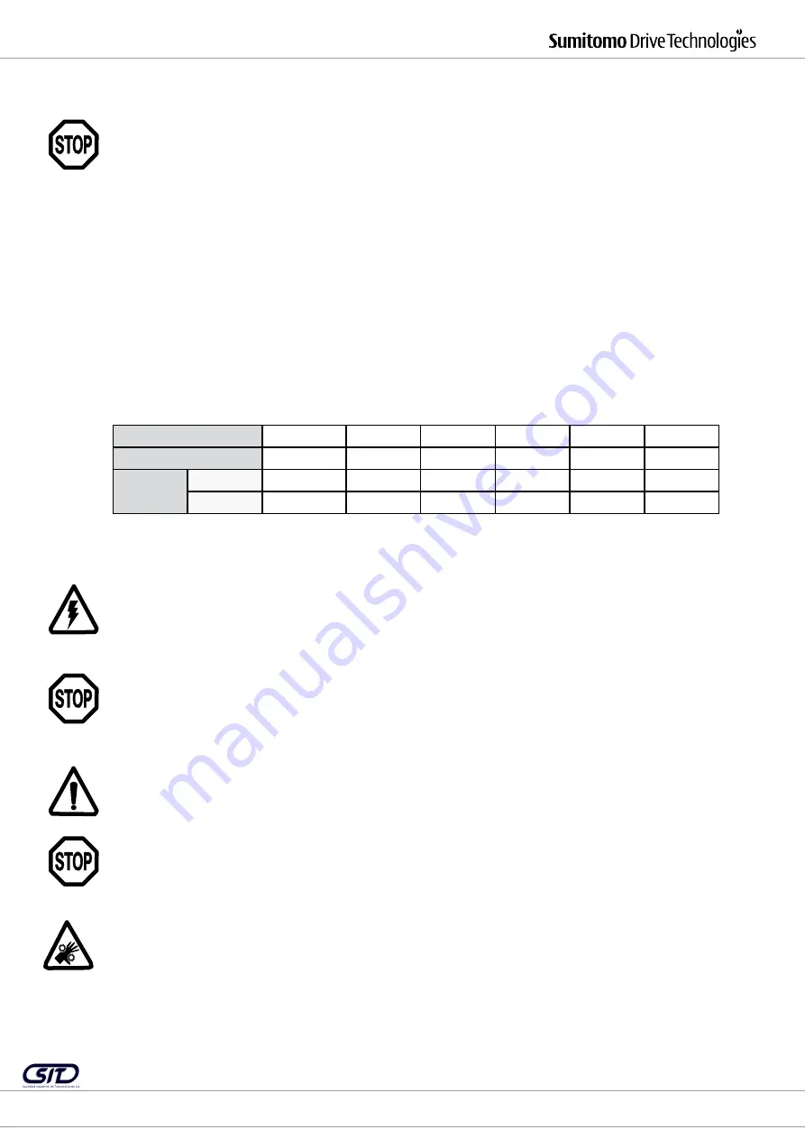
5.2 Installation

Table 1 Mounting screw torques

* Screw class ISO 898-1/8.8

Mos2 paste is recommended for preventing electrochemical corrosion between the PARAMAX SFC gear 
and the work machine when different metals are connected together, for example cast iron and stainless 
steel. 
The housing should also be grounded, using the grounding screws on the motor.

If the drive is to be painted over or partially re-finished, first ensure that the vent valve and shaft seals 
are carefully masked off. Remove the masking tape after the painting work is completed.

PARAMAX SFC gear units should not be used for any purposes other than those indicated on the model 
plate or in the manufacturer’s documentation; otherwise there is a risk of electric shocks, injuries, or 
damage to the equipment.

Do not place any inflammable objects near the unit, otherwise there is a risk of fire.

Do not place near the PARAMAX SFC gear unit any objects that obstruct the ventilation. Insufficient ven-
tilation can lead to overheating, and therefore a risk of burning or fire.

Do not step on or hold onto the PARAMAX SFC gear unit, as this may cause injuries.

Installation size

SFC045

SFC055

SFC060

SFC065

SFC070

SFC075

Screw size *

M24

M30

M30

M30

M36

M36

Torque

Nm

706

1400

1400

1400

2430

2430

in lbs

6250

12390

12390

12390

21510

21510

SIT S.A.     |      Tfno. 943 457200     |     [email protected]     |      www.sitsa.es

SIU 8320-00

            Instrucciones de instalación y mantenimiento Reductores PARAMAX SFC para Torres de Refrigeración

20/03/2018

Summary of Contents for PARAMAX SFC

Page 1: ...ars for Cooling Towers Betriebsanleitung Operation Manual Nr 991131 11 2009 SIT S A Tfno 943 457200 atencioncliente sitsa es www sitsa es SIU 8320 00 Instrucciones de instalaci n y mantenimiento Reduc...

Page 2: ...C Gear Unit 28 5 1 Required aids 28 5 2 Installation 29 5 3 Installation angle 29 5 4 Range of application 31 6 Connection to other Machines 31 6 2 Attaching a coupling element 31 6 1 Using the gear u...

Page 3: ...ance inspection etc read through these operating instructions carefully so that you understand exactly how to operate the PARAMAX SFC gear unit and know the safety regulations to be followed and warni...

Page 4: ...uctions for Operation with Motor Frequency Converter If a drive motor is connected to the PARAMAX SFC gear unit it should be put into operation only after checking that the data on the gear unit model...

Page 5: ...Once the PARAMAX SFC gear unit has been installed in the system never lift the whole machine using the suspension hooks or holes this can cause injuries damage to the equipment or damage to the lift i...

Page 6: ...details Gear reduction Input power Input rpm Serial number Fig 1 Service factor Series Size Output torque kNm Transmission stages Lubrication Shaft ar rangement Accessories Nominal ratio SFC 045 10 0...

Page 7: ...20 or equivalent product following the recommendations of the product manufacturer 5 Installation of the Paramax SFC Transmission 5 1 Required Aids Wrench set Torque wrench for mounting bolts on foot...

Page 8: ...l corrosion between the PARAMAX SFC gear and the work machine when different metals are connected together for example cast iron and stainless steel The housing should also be grounded using the groun...

Page 9: ...id and no liability can be accepted The installation angle should be within the limits indicated below Fig 2 Limit values for installation angle Standard units in the PARAMAX SFC gears and gear motors...

Page 10: ...ly if a reverse lock is installed Check the direction of rotation of the connected motor If the directions of rotation are different there is a risk of injuries or damage to the machine If the PARAMAX...

Page 11: ...e unit An oil flow switch and or inspection glass should be installed in order to check that lubricant is circulat ing correctly In case of emergencies switch off the motor The dimensions A B and X sh...

Page 12: ...vel Add oil through the filler neck at the top of the main unit checking the oil level with an oil gauge see Fig 5 Filter the oil before filling During oil filling take care to ensure that no loose nu...

Page 13: ...oil level is correct the transmission has been correctly connected to the other machines the anchor bolts are correctly tightened direction of rotation is as indicated in the specification all electri...

Page 14: ...ing a dipstick or oil level gauge Tab 6 Oil quantities Ambient temperature 15 40 C 15 40 C 0 40 C 40 C Oil heating with without without without Lubricant Mineral oil Synthetic oil Mineral oil Syntheti...

Page 15: ...t otherwise there is a danger of electric shock and injuries due to rotating parts During maintenance or inspection keep away from rotating parts output shaft etc and do not touch them Loose clothing...

Page 16: ...t agent dealer or sales office 10 3 Yearly Inspections To Inspect the Gears Drain the oil Loosen the mounting bolts on the inspection cover Check the gear teeth visually for pitting and wear When plac...

Page 17: ...be no thicker than 1 mm and should be removed where necessary The customer s installed configuration should not obstruct the heat flow from the PARAMAX SFC gear unit due to convection and heat conduct...

Page 18: ...e switched off immediately and should not be put back in operation until they have been repaired If any modifications are made to the system or non original parts are used the warranty is invalid and...

Page 19: ...Key 4622 Tolerance ring 6001 Tapered roller bearing 6002 Tapered roller bearing 6003 Tapered roller bearing 6004 Tapered roller bearing 6009 Tapered roller bearing 6010 Spherical roller bearing 6502 O...

Page 20: ...e repaired at an authorized workshop Ambient temperature too high Improve the ventilation Damage to gears bearings etc due to overloading Have repaired at an authorized workshop Oil leakage In input o...

Page 21: ...voltage directive Machinery directive 2006 42 EC Low voltage directive 73 23 EC EMC 89 336 EC ATEX 94 9 EC Transmission CE mark no no no yes Declaration of conformity no no no yes Installation statem...

Reviews: