


Section 7
ILLUSTRATIONS AND PARTS LIST
53
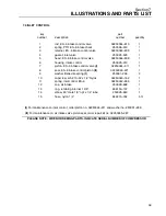
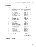
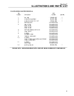
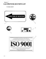
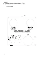
7.15 DECAL GROUP
key
part
number
description
number
quantity
1
decal, warning -- under pressure
(not shown)
02250078--001
1
2
decal, 3 position switch panel
(not shown)
250039--113
1
3
sign, warning -- hot surfaces
(not shown)
02250077--999
1
4
decal, warning auto start
(not shown)
02250077--473
1
5
decal, prohibition, breath/food
(not shown)
02250078--998
1
6
decal, Sullair logo (not shown)
02250059--052
1
7
decal, rotation direction
040745
1
8
decal, compressor fluid Sullube 32
(I)
02250069--389
1
8B
decal, fluid SRF 1/4000 (not shown)
(I)
02250069--391
1
9
decal, earth ground
02250075--046
2
S
decal, protective earth ground (not shown)
02250075--045
1
S
decal, PE designation (not shown)
02250075--540
1
10
decal, ES--6 Model (not shown)
02250060--043
1
11
decal, ISO 9001
02250059--288
1
12
decal, voltage international
(II)
02250069--397
1
(Continued on page 55)
(I)
Decal will change with fluid requirement.
(II)
Decal will vary with machine voltage. If voltage is not known, consult factory with serial number of com-
pressor.
PLEASE NOTE: WHEN ORDERING PARTS, INDICATE SERIAL NUMBER OF COMPRESSOR
Summary of Contents for ES-6 series
Page 6: ...NOTES...
Page 30: ...Section 7 ILLUSTRATIONS AND PARTS LIST 24 ES 6 COMPRESSOR ASSEMBLY EXPLODED VIEW 5 5 AND 7 5KW...
Page 32: ...Section 7 ILLUSTRATIONS AND PARTS LIST 26 7 3 FLUID MANAGEMENT SYSTEM...
Page 34: ...Section 7 ILLUSTRATIONS AND PARTS LIST 28 7 4 INLET FILTER...
Page 36: ...Section 7 ILLUSTRATIONS AND PARTS LIST 30 7 5 SEAL AND DRIVE GEAR...
Page 38: ...Section 7 ILLUSTRATIONS AND PARTS LIST 32 7 6 MOTOR HOUSING AND PARTS 7 5 10HP 5 5 7 5KW ONLY...
Page 42: ...Section 7 ILLUSTRATIONS AND PARTS LIST 36 7 8 COMPRESSOR SYSTEM...
Page 44: ...Section 7 ILLUSTRATIONS AND PARTS LIST 38 7 9 INLET CONTROL...
Page 46: ...Section 7 ILLUSTRATIONS AND PARTS LIST 40 7 10 CONTROL BOX...
Page 48: ...Section 7 ILLUSTRATIONS AND PARTS LIST 42 7 10 CONTROL BOX...
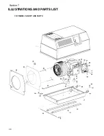
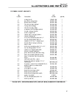
Page 52: ...Section 7 ILLUSTRATIONS AND PARTS LIST 46 7 12 FRAME CANOPY AND PARTS...
Page 56: ...Section 7 ILLUSTRATIONS AND PARTS LIST 50 7 14 WYE DELTA ELECTRIC BOX ES 6...
Page 58: ...Section 7 ILLUSTRATIONS AND PARTS LIST 52 7 15 DECAL GROUP 7 8 9 11 12...
Page 60: ...Section 7 ILLUSTRATIONS AND PARTS LIST 54 7 15 DECAL GROUP 13...
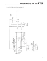
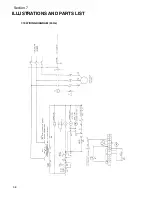
Page 62: ...Section 7 ILLUSTRATIONS AND PARTS LIST 56 7 16 WIRING DIAGRAM SINGLE PHASE 60Hz...
Page 63: ...Section 7 ILLUSTRATIONS AND PARTS LIST 57 7 17 WIRING DIAGRAM THREE PHASE 60Hz...
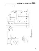
Page 64: ...Section 7 ILLUSTRATIONS AND PARTS LIST 58 7 18 WIRING DIAGRAM 50 Hz...
Page 65: ...Section 7 ILLUSTRATIONS AND PARTS LIST 59 7 19 WIRING DIAGRAM 50 Hz WYE DELTA...
Page 66: ...NOTES...
Page 67: ...NOTES...


