


Section 7
ILLUSTRATIONS AND PARTS LIST
35
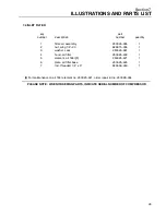
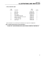
7.7 COMPRESSOR COOLER SYSTEM
key
part
number
description
number
quantity
1
duct, cooler mount (5HP/4KW)
250026--472
1
S
duct, cooler mount
(7.5HP and 10HP/5.5 and 7.5KW)
250026--471
1
2
ring, cooler (5HP/4KW)
250034--535
1
S
ring, cooler
(7.5HP and 10HP/5.5 and 7.5KW)
250034--536
1
3
screw, hex serrated washer 1/4”--20 x 1/2”
829704--050
8
4
screw, hex serrated washer 1/4” x 3/4”
829704--075
4
5
plate, cooler filler (5HP/4KW)
250025--829
1
S
plate, cooler filler
(7.5HP and 10HP/5.5 and 7.5KW)
250026--843
1
6
nut, hex 5/16”--18 (5HP/4KW)
825305--283
1
S
nut, hex 5/16”--18
(7.5 and 10HP/5.5 and 7.5KW)
825305--283
2
7
cooler, fluid (5HP/4KW)
250028--961
1
S
cooler, fluid and aftercooler
(7.5&10HP/5.5 and 7.5KW)
(I)
250026--066
1
8
orifice, fan ring 12 3/8” id
250034--537
1
9
capscrew, ferry 5/16”--18 x 1 1/2” (5HP/4KW) 828405--150
1
capscrew, ferry 5/16”--18 x 2”
(7.5HP &10HP/5.5 and 7.5KW)
828405--200
2
10
washer, flat 5/16”id x 1 1/4”od (5HP/4KW)
250025--830
1
S
washer, flat 5/16”id x 1 1/4”od
(7.5 & 10HP/5.5 and 7.5KW)
250025--830
2
11
connector, tube straight threaded 1/2” x 3/4”
811808--075
2
12
tube, 1/2”od (5HP/4KW)
250026--718
1
13
tube, 1/2”od
250030--040
1
14
cap, 1/2” tube
250026--350
1
15
tee, tube union 1/2”
811408--050
1
16
tube, 1/2”od (5HP/4KW)
250026--719
1
S
tube, 1/2”od
(7.5HP and 10HP/5.5 and 7.5KW)
250030--041
1
17
guard, 12” fan
250028--964
1
18
cap, fan guard 4”
250026--591
1
19
fan, 12” diameter (5HP/4KW)
250026--253
1
S
fan, 12” diameter
(7.5HP and 10HP/5.5 and 7.5KW)
250026--254
1
20
elbow, 90
q
connector 7/8”--14 x 1/2”npt
250030--104
1
21
elbow, tube straight threaded 5/8” x 7/8”
(7.5 and 10HP/5.5 and 7.5KW)
811615--062
1
22
tubing, aftercooler in
(7.5 and 10HP/5.5 and 7.5KW)
250030--042
1
23
tubing, fluid cooler out
(7.5 and 10HP/5.5 and 7.5KW)
250030--043
1
24
screw, brass set
250031--014
1
25
insert, 1/4”--20 threaded blind
250034--538
8
(I)
ES--6 1/2” npt service connection kit no. 250030--103.
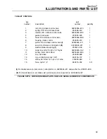
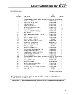
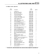
PLEASE NOTE: WHEN ORDERING PARTS, INDICATE SERIAL NUMBER OF COMPRESSOR
Summary of Contents for ES-6 series
Page 6: ...NOTES...
Page 30: ...Section 7 ILLUSTRATIONS AND PARTS LIST 24 ES 6 COMPRESSOR ASSEMBLY EXPLODED VIEW 5 5 AND 7 5KW...
Page 32: ...Section 7 ILLUSTRATIONS AND PARTS LIST 26 7 3 FLUID MANAGEMENT SYSTEM...
Page 34: ...Section 7 ILLUSTRATIONS AND PARTS LIST 28 7 4 INLET FILTER...
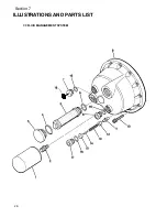
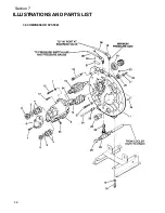
Page 36: ...Section 7 ILLUSTRATIONS AND PARTS LIST 30 7 5 SEAL AND DRIVE GEAR...
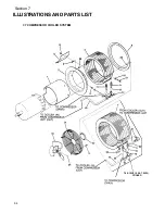
Page 38: ...Section 7 ILLUSTRATIONS AND PARTS LIST 32 7 6 MOTOR HOUSING AND PARTS 7 5 10HP 5 5 7 5KW ONLY...
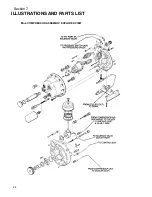
Page 42: ...Section 7 ILLUSTRATIONS AND PARTS LIST 36 7 8 COMPRESSOR SYSTEM...
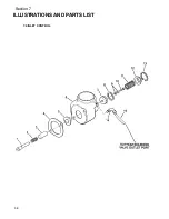
Page 44: ...Section 7 ILLUSTRATIONS AND PARTS LIST 38 7 9 INLET CONTROL...
Page 46: ...Section 7 ILLUSTRATIONS AND PARTS LIST 40 7 10 CONTROL BOX...
Page 48: ...Section 7 ILLUSTRATIONS AND PARTS LIST 42 7 10 CONTROL BOX...
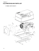
Page 52: ...Section 7 ILLUSTRATIONS AND PARTS LIST 46 7 12 FRAME CANOPY AND PARTS...
Page 56: ...Section 7 ILLUSTRATIONS AND PARTS LIST 50 7 14 WYE DELTA ELECTRIC BOX ES 6...
Page 58: ...Section 7 ILLUSTRATIONS AND PARTS LIST 52 7 15 DECAL GROUP 7 8 9 11 12...
Page 60: ...Section 7 ILLUSTRATIONS AND PARTS LIST 54 7 15 DECAL GROUP 13...
Page 62: ...Section 7 ILLUSTRATIONS AND PARTS LIST 56 7 16 WIRING DIAGRAM SINGLE PHASE 60Hz...
Page 63: ...Section 7 ILLUSTRATIONS AND PARTS LIST 57 7 17 WIRING DIAGRAM THREE PHASE 60Hz...
Page 64: ...Section 7 ILLUSTRATIONS AND PARTS LIST 58 7 18 WIRING DIAGRAM 50 Hz...
Page 65: ...Section 7 ILLUSTRATIONS AND PARTS LIST 59 7 19 WIRING DIAGRAM 50 Hz WYE DELTA...
Page 66: ...NOTES...
Page 67: ...NOTES...


