


SECTION 5
300HH, 375, 375H, 375HH, 425 AND 425H USER MANUAL R00
69
F
IRST
AND
S
ECOND
S
TAGE
D
ISCHARGE
A
IR
F
ILTER
M
AINTENANCE
—A
FTERCOOLED
&
F
ILTERED
M
ODELS
G
ENERAL
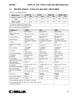
Refer to
. Familiarity with the filtration
process and the unit’s monitoring system (consisting
of a compete set of gauges) will enable the operator
to locate and analyze malfunctions.
The first and second stage filter element should be
changed when the pressure drop reaches the red
band on the pressure differential gauge.
D
AILY
O
PERATION
Check the automatic drain trap daily to ensure it is
operating properly.
F
IRST
AND
S
ECOND
S
TAGE
E
LEMENT
R
EPLACEMENT
1. Depressurize the filter and remove the filter
housing.
2. Remove the element.
3. Clean the inside of the filter housing, if nec-
essary.
4. Install a new element and gaskets
(P/N 02250153-294 FIRST STAGE)
(P/N 02250153-305 SECOND STAGE)
5. Reassemble the unit and check for air leaks.
6. Record the initial pressure drop when the
compressor is started.
S
AFETY
T
OXIC
A
ND
I
RRITATING
S
UBSTANCES
DO NOT use air from this filter as a source for
respiration (breathing air) except when in compliance
with OSHA STANDARDS 29 CFR 1910, and all other
applicable Federal, state, or local codes or
regulations.
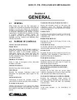
1. O-Ring
2. Filter Element
3. Filter Housing
Figure 5-7: First and Second Stage Discharge Air
Filter (Optional)
These filters will not remove water vapor, oil vapor,
carbon monoxide, or other toxic gases.
The first stage filter efficiently removes contaminants
such as ash, dust, water aerosols, lubricant mist,
carbon particles, rust and other contaminants (0.3
microns and larger).
The second stage filter removes particulates and all
lubricant aerosols of 0.01 micron size and larger.
D
ESIGN
R
ATINGS
Design ratings are 150°F (66°C) maximum air inlet
temperature. All welded filter housings are code
stamped for 250 psig (17.3 bar) maximum working
pressure.
WARNING
Death or serious injury can result from
inhaling compressed air without using
proper safety equipment. (See applicable
OSHA Standards)
1
1
2
3
SU_0000680
Summary of Contents for 300HH
Page 17: ...SECTION 1 15 Safety Symbols 2 ...
Page 18: ...SECTION 1 16 Safety Symbols 3 ...
Page 49: ...SECTION 2 300HH 375 375H 375HH 425 AND 425H USER MANUAL R00 47 2 9 WIRING DIAGRAM ...
Page 60: ...NOTES 58 ...
Page 79: ...NOTES ...