TFG2900A Series Function/Arbitrary Waveform Generator Users’ Guide
Suin Instruments Co., Ltd
28
dBm
=
10×log
10
(P/0.001)
P
=
(Vrms)
2
/Load
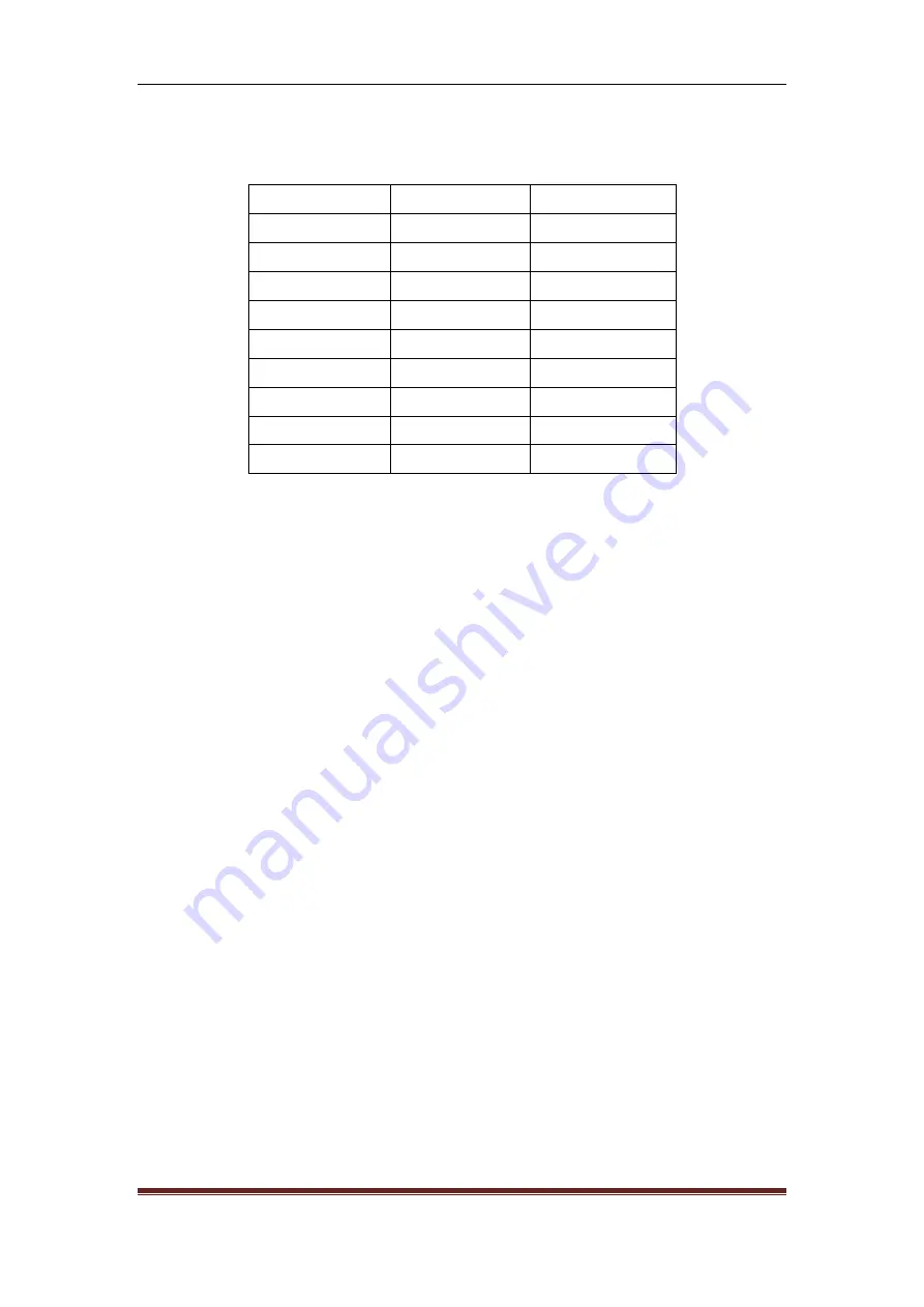
When it is Sine, external load is 50Ω, Vpp,Vrms and dBm are as following:
Vpp
Vrms
dBm
10.000 Vpp
3.5355Vrms
23.979 dBm
6.3246 Vpp
2.2361Vrms
20.000 dBm
2.8284 Vpp
1.0000Vrms
13.010 dBm
2.0000 Vpp
707.1 mVrms
10.000 dBm
1.4142 Vpp
500.0 mVrms
6.9897 dBm
632.5 mVpp
223.6 mVrms
0.00 dBm
282.8 mVpp
100.0 mVrms
-6.9897 dBm
200.0 mVpp
70.7 mVrms
-10.000 dBm
10.0 mVpp
3.5 mVrms
-36.020 dBm
3.2.8 Offset setting
: In continuous mode menu, press
〖
Offset/Low
〗
, choose ‘offset’ to set DC
offset value. It is limited by amplitude and limit level, which should conform to the following
formula:
DC offset≥low level limit+amplitude Vpp value/2
DC offset≤high level limit-amplitude Vpp/2
If DC offset exceeds the formula stipulated, instrument will modify it to limit it to the allowable
value.
While using knobs to adjust DC offset is easier than operation using number keypad. No matter
DC offset is positive value or negative value, switch the knob to right, DC level will incerease,
while it will decrease when switch it to left. When it goes through 0, offset value’s symbol will
change automatically.
3.2.9 Phase setting
: In continuous mode menu, press
〖
Phase
〗
to set output the phase. Output
phase means the phase difference that output signal relative to sync signal.
3.2.10 Polarity setting
: In continuous mode menu, press
〖
OutputMenu
〗
then press
〖
Polarity
〗
to
set the output signal’s polarity.
If you select ‘Positive’, output signal’s polarity will be positive. Take Sine for example, positive
polarity means waveform starts from 0 phase and voltage keeps rising status.
If you select ‘Negative’, output signal’s polarity will be negative. Negative polarity takes 0V
voltage as axis, reverse the waveform of positive polarity, which is vertical mirror to positive


