Kit Components
•
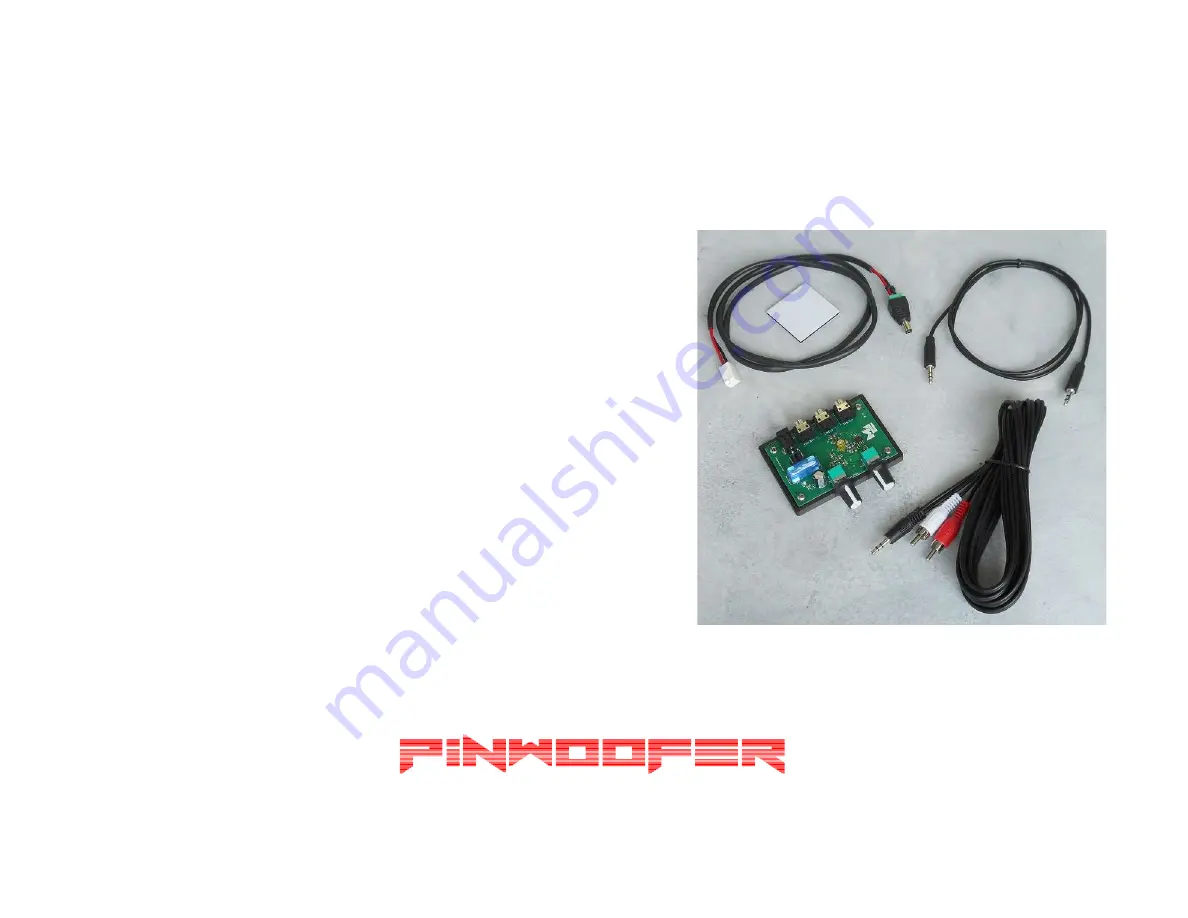
Shown to the right are the kit
components:
1. PinWoofer BBU Board2. 3ft 3.5mm Male to Male TRS Cable3. 3ft Power Cable4. 12ft 3.5mm TRS Male Stereo to RCA
Male Stereo Subwoofer Cable
5. Adhesive Double Sticky Mounting Pad.
Page 1: ...roduction transmission or redistribution of this document or its contents without written permission is prohibited Take your time follow the instructions relax and enjoy yourself WARNINGS Perform installation with your pinball machine turned off and unplugged from AC power ...
Page 2: ...PinWoofer KO and GT BBU Amplifier Instructions ...
Page 3: ...hown to the right are the kit components 1 PinWoofer BBU Board 2 3ft 3 5mm Male to Male TRS Cable 3 3ft Power Cable 4 12ft 3 5mm TRS Male Stereo to RCA Male Stereo Subwoofer Cable 5 Adhesive Double Sticky Mounting Pad ...
Page 4: ...olume and Bass Frequency Cutoff and provides a line out to your external subwoofer The first time you use the BBU please rotate both Bass Volume and Bass Frequency Cutoff controls fully counterclockwise so that you start from a quiet position and do not overdrive your external subwoofer when the title sound comes on ...
Page 5: ...Amplifier Identification This document covers BBU installation on one of two possible amplifier models Identify your amplifier as shown to the right Section 1 PinWoofer KO Section 2 PinWoofer GT ...
Page 6: ...Section 1 KO Amplifier ...
Page 7: ...Starting PinWoofer KO Amplifier Connections Shown to the right are 1 Harness Power Cable Connection 2 Harness Audio Cable Connection ...
Page 8: ...arness Audio Cable 3 5mm Male Mini Plug from the PinWoofer Amplifier Input and plug it into the LINE_IN jack on the BBU 5 Connect the 3ft 3 5mm Male to 3 5mm TRS Male Cable from the BBU LINE_OUT to the PinWoofer Amplifier Input Jack The image shows a 6in cable to minimize clutter 6 Plug the 12ft Subwoofer Cable into the SUB_OUT jack on the BBU 7 CAUTION Please examine the red and black wire orient...
Page 9: ...Section 2 GT Amplifier ...
Page 10: ...Starting PinWoofer GT Amplifier Connections Shown to the right are 1 Harness Power Cable Connection 2 Amplifier Output Mini Jack ...
Page 11: ...the New Power Cable Stub into the 5 5mm amplifier power jack 4 Connect the 3ft 3 5mm Male to 3 5mm Male Cable from the BBU LINE_IN to the PinWoofer GT Amplifier Line Out Jack The image shows a 6in cable to minimize clutter 5 Plug the 12ft Subwoofer Cable into the SUB_OUT jack on the BBU 6 The BBU LINE_OUT is unused 7 CAUTION Please examine the red and black wire orientation at the header labeled 2...
Page 12: ...ear maximum It is also recommended that you run the bass cutoff frequency LOW PASS Hz at maximum Both Volume and Low Pass functions are now controlled by the BBU If your subwoofer has a phase switch you ll want to first try it at 180 degrees Feel free to experiment It is recommended that you enable the auto power to on so that your external subwoofer turns off after a period of no signal at the in...
Page 13: ...e of how you might place your BBU into your machine using the KO Amplifier Keep in mind that there is power to your BBU so care should be taken to secure it to an interior surface using the supplied double sticky tape similar to what is shown ...
Page 14: ...e of how you might place your BBU into your machine using the GT Amplifier Keep in mind that there is power to your BBU so care should be taken to secure it to an interior surface using the supplied double sticky tape similar to what is shown ...
Page 15: ...Your PinWoofer BBU is now ready for use ...