background image

44

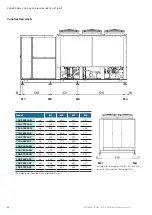
M1 M2  M3 

M4 

M5

Mxl Mxr

Modell

M1

M2

M3

M4

M5

CSO 4602 ASN

kg

549

670

631

713

319

CSO 5002 ASN 

kg

499

601

594

707

320

CSO 5902 ASN

kg

566

696

656

762

341

CSO 4602 ASF

kg

550

745

810

971

430

CSO 5002 ASF 

kg

505

677

772

961

428

CSO 5902 ASF

kg

569

773

836

1022

450

CQO 4002 ASN

kg

499

599

570

640

296

CQO 4602 ASN

kg

554

676

637

720

322

CQO 5002 ASN

kg

504

607

600

714

323

CQO 4002 ASF

kg

522

685

752

890

424

CQO 4602 ASF

kg

555

752

818

980

434

CQO 5002 ASF

kg

510

683

779

970

432

 EN/06.2018/G42  © STULZ GmbH – all rights reserved

cybercool 2 scroll original insTrUcTions

Construction size 7

The weights are indicated with a tolerance of ±5%.

Model

The weight on the support Mxr (M1, M2, M3 ... M5) is 
equal to the weight on the support Mxl.

Summary of Contents for CQO 1102 ASF

Page 1: ...CyberCool 2 Original instructions Precision Chillers Scroll compressor 400V 50Hz 3Ph N PE Index G42 Issue 6 2018...

Page 2: ...of its air conditioning technology business spe cialising in A C for data centres and telecommunications installations STULZ has seven production plants Germany Italy the USA 2 in China Brazil and In...

Page 3: ...erfrom STULZ The units which were produced in Hamburg have been developed especiallyfor use in Data Cen ters and industry and satisfy all requirements for efficiency and reliability For general inquir...

Page 4: ...4 4 EN 06 2018 G42 STULZ GmbH all rights reserved CYBERCOOL 2 SCROLL ORIGINAL INSTRUCTIONS...

Page 5: ...itioning 37 5 2 Weights on the supports 39 5 3 External water circuit 45 5 4 Electrical connection 51 6 Commissioning 56 6 1 Filling ofthe water circuit 56 6 2 Control ofthe electrical box 58 6 3 Oil...

Page 6: ...ntly available at the place where the system is used danger Works have to be carried out by competent staff only Safety devices may not be bypassed 1 3 Handling refrigerants Get qualified refrigeratio...

Page 7: ...protocol must be kept b To be stored in the proximity ofthe unit c Access for competent staff in case of repairs and repeated inspection must be ensured Repeated inspection according to EN 378 The op...

Page 8: ...tions must be checked country specifically notice When delivery is accepted check the unit against the consignment papers for completeness and for external damage and record it on the consignment pape...

Page 9: ...4 Forthe transport there are openings in the base frame through which steel tubes must be pushed The steel tubes are not delivered and must be provided bythe customer Requirements for the steel tubes...

Page 10: ...1 ASF 999 627 1079 EN 06 2018 G42 STULZ GmbH all rights reserved cybercool 2 scroll original INSTRUCTIONS G unit transport weight S centre of gravity Construction size 3 The co ordinates ofthe centre...

Page 11: ...650 1442 CQO 1102 ASN 1702 630 1565 CQO 802 ASF 1730 760 1722 CQO 1102 ASF 1785 736 1849 STULZ GmbH all rights reserved EN 06 2018 G42 cybercool 2 scroll original INSTRUCTIONS G unit transport weight...

Page 12: ...st oftwo cross beams with a minimum length of 2400 mm The drawings on the following pages showthe dimensions forthe suspension points and the position ofthe centre of gravity Suspension at the lifting...

Page 13: ...QO 1302 ASN 1680 2808 CQO 1602 ASN 1710 3112 CQO 1902 ASN 1720 3154 CQO 1302 ASF 1920 3247 CQO 1602 ASF 1860 3555 CQO 1902 ASF 1860 3597 STULZ GmbH all rights reserved EN 06 2018 G42 cybercool 2 scrol...

Page 14: ...CQO 2402 ASN 2180 3713 CQO 2802 ASN 2200 3779 CQO 3702 ASN 1880 4319 CQO 2402 ASF 2290 4295 CQO 2802 ASF 2300 4366 CQO 3702 ASF 2000 4907 EN 06 2018 G42 STULZ GmbH all rights reserved cybercool 2 scro...

Page 15: ...CSO 4202 ASF 2660 5374 STULZ GmbH all rights reserved EN 06 2018 G42 cybercool 2 scroll original INSTRUCTIONS Construction size 6 The co ordinates ofthe centre of gravity are indicated with a toleranc...

Page 16: ...CQO 4002 ASN 2790 5035 CQO 4602 ASN 2630 5558 CQO 5002 ASN 2830 5234 CQO 4002 ASF 3095 6017 CQO 4602 ASF 2950 6542 CQO 5002 ASF 3130 6207 EN 06 2018 G42 STULZ GmbH all rights reserved cybercool 2 scro...

Page 17: ...rotection grille the protection grilles must be unscrewed to remove the polypropylene plates Remove these plates before start up Coil protection grille optional housing protection grille optional Opti...

Page 18: ...max BP 14 bar Temperatur min max Temperature min max Temp rature min max 10 100 C R410A 0098 C S O 280 2 A S N EN 06 2018 G42 STULZ GmbH all rights reserved cybercool 2 scroll original INSTRUCTIONS F...

Page 19: ...is designed for outdoor installation Any use beyond this is not deemed to be use as intended STULZ is not liable for any damage resulting from such misuse The operator alone bears the risk The chiller...

Page 20: ...n CSO CQO _ _ _ _ ASF This version additionally contains a free cooling coil for each refrigerant circuit The free cooling coils are con nected in parallel in the water side circuit During free coolin...

Page 21: ...compressor contains a crankcase heater Electric cabinet The electric cabinet is divided into a load section and a control section with separate door The load section contains a power switch operable...

Page 22: ...tion gas pressure evaporation pressure Chilled water circuit chilled water inlet temperature chilled water outlet temperature flow sensor frost protection thermostat intermediate temperature free cool...

Page 23: ...ectric network or UPS system must be grounded neutral wye the voltage distortions must be within the limits stated below and no inadmissibly high DC voltage portions may exist transient peak over volt...

Page 24: ...Wasservolumenstom c m h 5 8 6 6 8 3 11 5 14 2 17 5 Modellreihe CQO ASN 1 1902 2402 2802 3702 4002 4602 5002 Max Au entemperatur a C 45 5 47 4 45 8 42 5 47 4 45 9 44 9 max Wasservolumenstom b m h 42 4...

Page 25: ...d water quality Models CQO ASF 2 Max outdoortemperature a C max watervolume flow b m h min watervolume flow c m h Models CQO ASF 2 Max outdoortemperature a C max watervolume flow b m h min watervolume...

Page 26: ...Sound pressure level full load in 1m distance underfree field conditions according to ISO 3744 3 Sound power level full load underfree field conditions according to ISO 3744 4 Water inlet temperature...

Page 27: ...3 4 8 4 Nennstrom A 2 9 5 6 12 8 Ger tedaten Spannungsversorgung 400V 50Hz 3Ph N PE Betriebsstrom OA 1 A 26 1 29 4 38 2 52 1 58 8 80 7 90 5 maximaler Betriebsstrom RLA A 32 3 36 8 45 2 63 6 72 7 99 3...

Page 28: ...nnleistung kW 8 4 12 6 15 4 21 Nennstrom A 12 8 19 2 25 6 32 Ger tedaten Spannungsversorgung 400V 50Hz 3Ph N PE Betriebsstrom OA 1 A 116 8 146 3 178 0 191 188 4 219 9 236 9 283 5 maximaler Betriebsstr...

Page 29: ...3 8 Nennleistung kW 1 9 7 4 11 5 Nennstrom A 2 9 11 4 17 6 Ger tedaten Spannungsversorgung 400V 50Hz 3Ph N PE Betriebsstrom OA 1 A 27 1 30 5 39 3 54 3 60 9 83 7 93 5 maximaler Betriebsstrom RLA A 35 2...

Page 30: ...eleistung kW 8 11 9 15 9 19 9 Nennleistung kW 11 5 17 3 23 28 8 Nennstrom A 17 6 26 4 35 2 44 Ger tedaten Spannungsversorgung 400V 50Hz 3Ph N PE Betriebsstrom OA 1 A 119 7 150 7 182 5 195 5 193 3 227...

Page 31: ...r tedaten Spannungsversorgung 400V 50Hz 3Ph N PE Betriebsstrom OA 1 A 25 9 29 9 34 2 51 8 56 3 77 3 maximaler Betriebsstrom RLA A 32 3 36 8 47 5 63 6 79 9 99 3 Kurzschlussstrom LRA A 124 5 133 5 101 1...

Page 32: ...21 Nennstrom A 12 8 19 2 32 Ger tedaten Spannungsversorgung 400V 50Hz 3Ph N PE Betriebsstrom OA 1 A 88 8 109 1 142 8 178 7 177 3 213 3 232 5 maximaler Betriebsstrom RLA A 112 9 144 4 176 5 208 4 234 2...

Page 33: ...ennstrom A 5 7 11 4 17 6 Ger tedaten Spannungsversorgung 400V 50Hz 3Ph N PE Betriebsstrom OA 1 A 25 9 29 9 34 2 51 8 56 3 77 3 maximaler Betriebsstrom RLA A 32 3 36 8 47 5 63 6 79 9 99 3 Kurzschlussst...

Page 34: ...tung kW 11 5 17 3 28 8 Nennstrom A 17 6 26 4 44 Ger tedaten Spannungsversorgung 400V 50Hz 3Ph N PE Betriebsstrom OA 1 A 88 8 109 1 142 8 178 7 177 3 213 3 232 5 maximaler Betriebsstrom RLA A 112 9 144...

Page 35: ...00 1300 2350 1300 2350 3950 2300 2510 STULZ GmbH all rights reserved EN 06 2018 G42 cybercool 2 scroll original INSTRUCTIONS 4 3 Dimensional drawings Construction size 3 Construction size 4 Constructi...

Page 36: ...36 5030 7250 6170 2300 2510 2300 2510 2300 2510 EN 06 2018 G42 STULZ GmbH all rights reserved cybercool 2 scroll original INSTRUCTIONS Construction size 6 Construction size 7 Construction size 6...

Page 37: ...y aerodynamically disadvantageous conditions 5 Installation 5 1 Positioning The fins ofthe air cooled free cooling coils are made of a high quality aluminum alloy Depending on the site an extended pro...

Page 38: ...original INSTRUCTIONS Maintenance clearance Space needed for individual installation and multiple unit installation Take into account the necessary clearances forthe maintenance and the airflow Keep a...

Page 39: ...173 CSO 801 ASF kg 228 178 134 233 214 181 CQO 541 ASN kg 222 170 120 195 158 126 CQO 621 ASN kg 222 173 123 198 160 128 CQO 541 ASF kg 226 175 127 228 205 173 CQO 621 ASF kg 230 177 129 229 208 175...

Page 40: ...253 154 215 399 366 216 CQO 802 ASN kg 121 213 229 115 140 270 246 143 CQO 1102 ASN kg 140 256 235 136 149 282 258 149 CQO 802 ASF kg 135 246 229 124 199 380 348 210 CQO 1102 ASF kg 150 270 248 148 2...

Page 41: ...QO 1302 ASN kg 385 460 390 196 CQO 1602 ASN kg 431 515 429 208 CQO 1902 ASN kg 436 525 440 214 CQO 1302 ASF kg 409 526 488 281 CQO 1602 ASF kg 451 588 535 289 CQO 1902 ASF kg 455 598 546 294 STULZ Gmb...

Page 42: ...QO 2402 ASN kg 445 587 627 239 CQO 2802 ASN kg 454 601 647 249 CQO 3702 ASN kg 533 732 734 244 CQO 2402 ASF kg 462 686 814 324 CQO 2802 ASF kg 464 703 842 320 CQO 3702 ASF kg 538 834 934 314 EN 06 201...

Page 43: ...4 CSO 4202 ASF kg 470 713 748 639 323 STULZ GmbH all rights reserved EN 06 2018 G42 cybercool 2 scroll original INSTRUCTIONS Construction size 6 The weight on the support Mxr M1 M2 M3 M5 is equal to t...

Page 44: ...0 CQO 4002 ASN kg 499 599 570 640 296 CQO 4602 ASN kg 554 676 637 720 322 CQO 5002 ASN kg 504 607 600 714 323 CQO 4002 ASF kg 522 685 752 890 424 CQO 4602 ASF kg 555 752 818 980 434 CQO 5002 ASF kg 51...

Page 45: ...ed ifthe watervolume ofthe water circuit is less than 10 litres kW cooling capacity The storage tank should be lined out with thermical insulation expansion tank with safetyvalve to ensure a possibili...

Page 46: ...option Outside temperature sensor Free cooling valves only forversions ASF AHF of construction sizes 5 7 Longer storage and standstill periods more than 1 month lead to the bonding ofthe valve flaps...

Page 47: ...truction size 3 Water outlet Water inlet Construction size 4 Size 3 4 Rearview Construction size 3 4 Chilled water connection G1 1 2 internal thread G2 1 2 internal thread Chilled water connection not...

Page 48: ...Construction size 6 Water inlet Water outlet Side view Rearview Construction size 5 6 Type CSO CSO 2802 CSO 3702 CSO 4002 Chilled water connection G2 1 2 internal thread DN 80 flange DN 80 flange DN...

Page 49: ...let Rearview Chilled water connection Construction size 6 Side view Construction size 6 Type CSO 4202 Chilled water connection DN 100 flange To avoid misunderstanding The designation water inlet and w...

Page 50: ...fthey get in contact with external air to prevent the introduction of heat from the ambient air as well as possible Remove the protective hoods from the water pipes Connect the external piping to the...

Page 51: ...average value ofthe voltages may not exceed 8 V danger Mortal danger by electric hazard Ensure that the power supply at the connection cable is de energized The electric cables are onlyto be connected...

Page 52: ...90 counterclockwise The door locking mecha nism will be released in doing so 4 The second door ofthe power section can be opened byturning the inner locking lever counterclockwise Electric cabinet key...

Page 53: ...e electric cabinet from the bottom The following bottom views displaythe apertures Size 3 Size 4 Air inlet Air inlet Reserve Option second power supply Power supply Grounding Condensate drain of el ca...

Page 54: ...ew Front side electric cabinet doors Entrance area for power supply Grounding point Connection of control lines optional Ifthe chiller shall be connected to other Stulz units bythe IO bus to a BMS or...

Page 55: ...load outlet for external pumps is also available as an optional extra notice Ifyou do not explicitly orderthe option On Off control for external pump the power supply to the external pumps cannot com...

Page 56: ...25 2 C 45 until 30 8 C 50 until 37 6 C Propylene glycol Water or outside airtemperature 25 until 10 7 C 30 until 14 0 C 35 until 17 6 C 40 until 21 5 C 45 until 26 0 C 50 until 32 4 C warning Risk of...

Page 57: ...n top ofthe free cooling coils The following drawing illustrates the diagonal arrangement system ofthe valves Remove the rubber plugs and also connect hoses here if necessaryto catch the mixture Begin...

Page 58: ...are now supplied with power so you can use it for adjustments 6 2 Control of the electrical box Make sure that the master switch is off and the unit is de energized Open the electrical compartment do...

Page 59: ...nal INSTRUCTIONS Electrical cabinet power section left side Compressor power switch circuit 1 Compressor power switch circuit 2 Main switch Condenserfan power switch cir cuit 1 Condenserfan power swit...

Page 60: ...ol 2 scroll original INSTRUCTIONS Electrical cabinet control section right side User interface with display Driver module for electro nic expansion valve plus battery module IO controller board Servic...

Page 61: ...value plus the hysteresis the frost pro tection mode is cancelled and normal operation is continued Factory setting Setpoint 4 C Controllertype typ Col Hysteresis 5 K Sensortype SEn P It Lead compensa...

Page 62: ...losed Ensure that the water system has been sufficientlyfilled and that all stop valves are open Check the sense of rotation ofthe pump and start the pump Ifthe pump is controlled bythe C7000 control...

Page 63: ...watervolume flow The following triggering values forthe minimum volume flow have been adjusted in the factory red LED adjusting screw flow sensor module You can modifythe triggering value forthe wate...

Page 64: ...evaporator outlet 12 C tflow tevap 12 C 5 0 C 7 K ok Ifthe tolerances 18 K at the condenser 7 K at the evaporator are exceeded there is a problem of heat trans mission The probable cause is the pollut...

Page 65: ...t is shut down switch offthe chiller at the controller and at the master switch display a DO NOT SWITCH ON warning sign switch off power conducting cables to the unit and secure them against being swi...

Page 66: ...gerant circuit resp the closed off section with nitrogen the circuit has to be run dry by several fillings and extractings with high quality nitrogen change the filter drier cartridge evacuate the ref...

Page 67: ...rier service valve HP switch high pressure limiter When the HP limitertriggers the compressor is switched offwithout delay Before the restart and afterthe elimination ofthe error the HP switch must be...

Page 68: ...valve The refrigerant circuit is equipped with an electronic expansion valve which controls the superheating in the evaporator The superheating is adjusted to 5 K at the factory and may not be modifi...

Page 69: ...ng Procedure first clean the coil with a vacuum cleaner and soft nozzle rinse from the inside out and from bottom to top direct the jet ofwater always vertically on the fins to not distort the fins al...

Page 70: ...wer line part and two screwed plug connections in the control line part disconnect the electrical connections and protect them against damage and humidity completely unscrewthe 4 Torx screws ofthe fan...

Page 71: ...eeds 7 K the evaporator is probably polluted In this case the evaporator has to be cleaned chemically 7 5 Water circuit Frost protection sensor Flow sensor Water outlet temperature sensor Water inlet...

Page 72: ...f pipes and circuit components can result in leaks check the pipes for a tight seat Condensing air humidity on cold water pipes means a loss of cooling capacity check the insulation ofthe water piping...

Page 73: ...oo low Check alimentation under load Compressor failure The soft start module option orthe protection device has detected an error Find the exact cause of error Sensor failure The tolerance to the ave...

Page 74: ...water side possibly in combination with return water control Check heat transmission at the evap orator by checking the temperature difference between flowwatertemp and evaporation temperature 3 Cond...

Page 75: ...p cabin temp too high The adjusted limit value has been exceeded 1 Ventilation grilles in the compres sor cabinet are blocked 2 The first condenser fan group of a refrigerant circuit is out of opera t...

Page 76: ...used this liquid has to be collected and disposed of in an appropriate manner and may under no circumstances be introduced in the local waste water system disconnect the unit from the external water...

Page 77: ...Lloyd SE Brooktorkai 18 D 20457 Hamburg STULZ GmbH all rights reserved EN 06 2018 G42 cybercool 2 scroll original INSTRUCTIONS hereby confirms that the units listed below in the version marketed by u...

Page 78: ...upports It is not necessaryto fix each anti vibration mount onto the support frame But in any case the four corner mounts should be screwed on The anti vibration mounts protrude the lateral dimensions...

Page 79: ...t while you fix the mounts The lower nut should be at the same height for all mounts Mark the position in advance on the threaded rod Then attach the anti vibration mount in accordance with the drawin...

Page 80: ...15 The unit height increases to 2500 mm in case of size 3 4 and to 2680 mm forthe construction sizes 5 7 The external diffusor ofthe AxiTop is attached bytwo M6x12 lens head screws at four points on t...

Page 81: ...bytwo cable ties at the support bracket opposite to the cable connection Warm air is aspirated from the motor housing bythe cooling tube Ifthe fan is entirely exchanged not onlythe motor it is approp...

Page 82: ...eserved cybercool 2 scroll original INSTRUCTIONS 11 3 Option lateral power supply With this option you can feed in the power supply cables from the right or left side Size 3 Size 4 Feed in from left F...

Page 83: ...83 max 3 x 65 max 3 x 65 STULZ GmbH all rights reserved EN 06 2018 G42 cybercool 2 scroll original INSTRUCTIONS Size 5 7 Feed in from left Feed in from right...

Page 84: ...an installation in an industrial environment located nearwaste incinerators orwaste watertreatment plants nearthe sea site within 20 km from the coast As the corrosion protection depends largely on th...

Page 85: ......

Page 86: ...57 ventas stulz com mx netherlands STULZ GROEP B V Tel 31 20 54 51 111 Fax 31 20 64 58 764 stulz stulz nl new zealand STULZ New Zealand Ltd Tel 64 9 360 32 32 Fax 64 9 360 21 80 sales stulz co nz pola...

Reviews: