background image

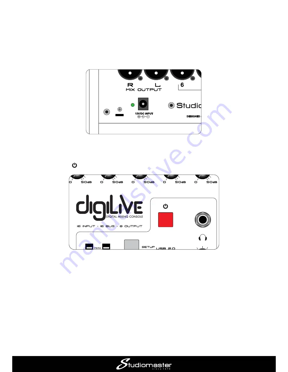
Powering your digiLiVE

Your 

digiLiVE

!"#$%&'  (

)+ &' / +(%  &'2%
mains supply with the cable supplied; it can operate on mains voltages from 100 V to 240 V. When 
the PSU is connected to AC mains, a blue LED on the PSU lights. The DC output cable should be 
plugged in to the 

12V/DC INPUT

 socket on 

digiLiVE

’s rear panel.

Once connected, 

digiLiVE

 starts its boot-up sequence as soon as you turn the AC mains on; this 

takes approximately 30 seconds.

The Power button  +  

 2 6   7) 289(: 

  <  / +=/  /
passed with all console settings retained;

 A short press when the console is in SAFE mode returns it to its normal operating state;

 2  6   7) <>

 2  6   788/ (

Whenever 

digiLiVE

 powers down, all current console settings are saved. Next time you power it 

up, 

digiLiVE

 will have exactly the same settings you last used.

Summary of Contents for digiLiVE

Page 1: ...digiLiVE Digital Mixing Console Quick Start Guide Issue 1 0 ...

Page 2: ......

Page 3: ...is Quick Start Guide is not intended as an alternative or replacement for the full digiLiVE User Guide which will either be in the box with the console or available to you as a free download As you work through the simple operating examples in the Quick Start Guide you ll almost certainly notice that the console includes a great many features and possibilities that are not covered here Once you ve...

Page 4: ...igiLiVE s rear panel Once connected digiLiVE starts its boot up sequence as soon as you turn the AC mains on this takes approximately 30 seconds The Power button 2 6 7 289 passed with all console settings retained A short press when the console is in SAFE mode returns it to its normal operating state 2 6 7 2 6 788 Whenever digiLiVE powers down all current console settings are saved Next time you p...

Page 5: ...tputs on digiLiVE are at standard line level and are electronically balanced digiLiVE s outputs NOTE It is always good practice to turn on interconnected audio devices in sequence In this case turn digiLiVE B digiLiVE 7 H avoid nasty loud bangs or thumps from the speakers Connection to passive speakers Connection to active speakers ...

Page 6: ...ing adjusted will be indicated on screen by a yellow border around its control to select a parameter for adjustment touch its control on the screen In the example below the ADJUST knob will pan the signal in Channel 1 between the left and right stereo channels Press a channel MUTE button to mute the channel and again to unmute You can plug headphones into the socket marked and use the SOLO buttons...

Page 7: ...igiLiVE s faders fully closed GAIN J This should ensure that no bangs or thumps will be heard from your system while you re setting everything up Application Example 1 solo performer This simple application would be suitable for a solo performer e g a singer instrumentalist It would also be appropriate for an AV situation such as in a school classroom or anywhere a presenter is using a laptop or s...

Page 8: ...connected directly using a standard guitar z J 8 J 7 J directly If you need to use a stereo source such as a laptop tablet or similar audio device it is most easily connected to STEREO input 2 which is available both in the form of a 3 5 mm jack socket and separate left and right jack sockets Making a mix digiLiVE J gain and then opening the channel and main faders On switching on INPUT 1 8 is sel...

Page 9: ...r Channel 1 and then tap the Input Mic IN Touch the 48V The 48V indicator at the top of the on screen channel strip turns to red to remind you that phantom power is on IMPORTANT Only turn phantom power on when condenser mics are in use Do not turn it on for J J ...

Page 10: ...to about the zero mark and move the MIX OUTPUT fader upwards You should hear the vocal mic when speaking into it and see a level indication on the MIX meters These meters monitor the console s output which is feeding the speakers Repeat the above procedure for Channel 2 which is receiving the signal from the instrument If you are using the STEREO 2 input for an audio source as described in Connect...

Page 11: ...ow control the remaining input channels and the screen follows the selection STEREO 2 8 panel is marked ST2 adjacent to the fader Set the input gain and open the channel fader in the same way as described for Channels 1 and 2 to access the controls for each ...

Page 12: ...ship digiLiVE has 12 mono channels to which microphones or line level sources can be connected _ Connecting up Amplifying a band will typically involve microphones DI boxes and line level sources Connect the convenient for mixing to have critical audio sources on the same layer STEREO 1 or STEREO 2 MICS DI BOXES BASS SYNTH WORKSTATION GUITAR SAX MIC ELECTROACOUSTIC GUITAR POWERED SPEAKERS L R ...

Page 13: ...ered active DI boxes as described in Application Example 1 Making a mix The factory default settings of digiLiVE let you mix directly to the stereo output so it is only necessary to adjust the GAIN controls for each input in use and open the input and MIX OUTPUT faders B J ...

Page 14: ...embers can hear themselves and other players as they wish digiLiVE lets you create up to six additional mono monitor mixes Connecting Up 2 9J OUTPUTS 1 to 6 For _ J OUTPUT 1 J J MICS POWERED MONITOR DI BOXES BASS SYNTH WORKSTATION GUITAR SAX MIC ELECTROACOUSTIC GUITAR POWERED SPEAKERS L R OUTPUTS 1 to 6 MIX OUTPUTS ...

Page 15: ...le s default routing are connected directly to the MIX OUTPUTS To create a separate monitor mix one of digiLiVE s further eight mix busses is also used 1 With the main screen for Channels 1 to 8 displayed press the SELECT button for the lead 2 Touch the blank area above the CH 1 ident strip 3 ...

Page 16: ... level sent to the monitor will be independent of the channel fader setting You can continue to adjust your FOH mix without altering the monitor mix 5 J the BUS 1 8 LAYER button Note that the Bus 1 you should be able to hear the vocal mic in the monitor ...

Page 17: ...rs in his her monitor mix repeat Steps 1 to 4 above for each of the other vocalists or instruments needed For example if the singer needs to hear the electroacoustic guitar in the example select Input Channel 4 in Step 1 and send some J You can build up a monitor mix like this with as many instruments as required The overall level 8 J channel ...

Page 18: ...mixes or a combination of the two IEM TRANSMITTER STEREO POWERED MONITOR 3 POWERED MONITOR 4 POWERED MONITOR 2 POWERED MONITOR 1 SIDE FILL SIDE FILL FREQ POWERED MONITOR 4 In the example shown we are using four powered wedge monitors are at the front of the stage 9 monitors to OUTPUTS 1 to 4 the IEM transmitter to OUTPUTS 5 and 6 MIX OUTPUTS L and R Making the mix digiLiVE s faders have a fourth l...

Page 19: ... send display for channel 1 providing increased detail for all the channel s bus sends It is now easy to set how much of the instrument or vocal in the input channel should go to each of the busses and thus to each output You can scroll through Channels 1 to 8 by pressing the SELECT INPUT 9 12 ST USB input channels ...

Page 20: ...FADER LEVELS DEFINE MONITOR MIX TO OUTPUT 1 INPUT CHANNEL 1 SELECTED LAYER 1 AND SEND MODE SELECTED FADER LEVELS DEFINE MONITOR MIX TO OUTPUT 4 INPUT CHANNEL 4 SELECTED LAYER 1 AND SEND MODE SELECTED ...

Page 21: ...Application Example 5 Enhancing the mix 5 1 Adding EQ _ H 9 quality Each digiLiVE input channel has a 4 band parametric EQ section Until you make an adjustment H 9 9 9 ...

Page 22: ...Freq or Q on screen control and use the ADJUST knob Tap the Gain Freq or Q dialling action 9 H _ bandwidth using this method You can cancel an EQ curve by tapping the Flat button tapping the Bypass button has the same 9 Note that a miniature version of the EQ curve for each input is displayed on the main channel page ...

Page 23: ...igiLiVE Adding compression to a vocal mic will aid audibility maintain a good level and help with poor mic H To access the dynamics controls for any channel touch the dynamics area of its channel strip to open the Dynamics sub page ...

Page 24: ... compressed The graph depicts J currently set up The Reduction meter to the right of the graph gives you an idea of how hard the compressor is working as you increase Ratio lower Threshold the channel GAIN _ When Ratio level will not exceed the value set with the Gain control The Attack and Release controls control how fast the compressor operates and are best adjusted quieter use the Gain control...

Page 25: ...omatic switch signals higher than the level set on the Threshold control pass through the gate quieter signals are rejected Adjust the Threshold control so that the snare drum is clearly audible when the drum is hit but there is no extraneous noise in between snare hits Threshold is probably most easily set using the channel s SOLO Attack Release and Hold _ compromise between a good drum sound and...

Page 26: ...ows you what the gate is doing the meter will show 0 dB when the gate is triggered and 80 dB idea of how the Attack Hold and Release Note that a miniature version of the dynamics section graphs for each input is displayed on the main channel page ...

Page 27: ...5 4 Adding reverb to your vocals digiLiVE 8 Press the SELECT button of the relevant input channel and then tap the topmost area of the Mic IN In the Insert section tap the Reverb 1 button ...

Page 28: ... SET UP button On the SET UP page tap the FX button on the left Double tap Reverb 1 Either tap a control and then use the ADJUST use a dialling action for the rotary knobs The amount of reverb is controlled by the Wet Dry slider and the reverberation time by the Time control Tap the arrow in the Type J J ...

Page 29: ...cal reverb plates 9 8 8 LS and HS of cut or boost the Freq H H Pre Delay original dry signal Note An alternative method of assigning reverb is to apply it to one of the STEREO ouput busses All channels that require reverb can then be routed to that STEREO output bus Full details can be found in the User Guide ...

Page 30: ...e downloaded from the Apple App Store in the usual way Search the store for Studiomaster Digilive You will need to set up a WiFi hotspot on the digiLiVE to establish communication between the iOS device and digiLiVE To do this Press the SET UP button On the screen tap the Setup button Select followed by More ...

Page 31: ... Select Portable hotspot followed by Setup Wi Fi hotspot 9 J DigiLive1 Tap the Save button ...

Page 32: ... tick the check box Press the BACK button to return to the digiLiVE mixer pages Once you ve downloaded the DigiLive 7 Open the Settings window Select the WiFi tab choose DigiLive1 and enter the password Open the DigiLive app ...

Page 33: ... Press NetScan J J J OK Select the mixer named OK and press Connect The DigiLive app is now available for use ...

Page 34: ......

Page 35: ......

Page 36: ...STUDIOMASTER Chippenham Drive 9 H B ...

Reviews: