background image


 23 

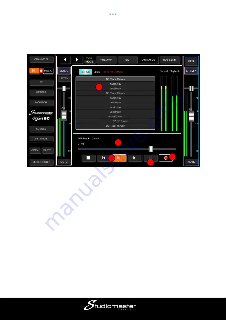
MUSIC PLAYER 


Touching the 

Music

 tab opens the Music Player and calls up the Music (USB 2.0) input. 


Track Listing 

Shows the names and file types of all mp3 and WAV files in the root directory of a USB drive 
inserted into the Music USB 2.0 channel connector. 
You can swipe or scroll through this list to check its contents or to select an individual track. 


Elapsed Time Cursor


Shows the current time position in the loaded audio file. Can be used to move forwards or 
backwards in time through a loaded file. 


Transport Controls


Buttons for Stop, Return to Start, Play and Go to End. Double-tapping Play causes playback 
to skip to the next track. 


Play Order


As default, audio files play sequentially through the order shown in the on-screen list. This 
control allows you to repeat the entire list, select shuffle play or to repeat the currently-
playing file. 


Record Control


Touching this button starts the recording of the Main Mix outputs (button changes to a round 
shape and “On Air” sign appears). Touching it again stops the recording (button changes 
back to a square shape and “On Air” sign disappears). 


1

2

3

4

5

Summary of Contents for digiLiVE 4C

Page 1: ...PICTURES OF 4C and 8C Issue 0 65 digiLiVE 4C and 8C Digital Mixing Consoles USER GUIDE...

Page 2: ...LS 9 Channel Controls 9 Main Mix Control 9 digiLiVE HTML CONTROL APPLICATION 10 HTML App Access Wi Fi 10 HTML App Access LAN 10 CHANNELS SCREEN 11 FULL MODE 11 BASIC MODE 12 LOCK MODE 12 INPUT CHANNEL...

Page 3: ...TS 28 GEQ PAGE 29 METERS PAGE 30 MONITOR PAGE 31 LISTEN 31 OSCILLATOR 32 SCENES PAGE 33 SETTINGS PAGE 35 NETWORK SUB PAGE 36 LOG SUB PAGE 39 MUTE GROUP SUB PAGE 40 FOOT SWITCH SUB PAGE 41 DIRECT FUNCT...

Page 4: ...It will take you on a tour through the operational features of these two mixers explaining in detail the function of each input output knob and switch Having done that the Guide will then show you ho...

Page 5: ...he digiLIVE power supply can operate on mains voltages from 100 V to 240 V When the PSU is connected to AC mains a blue LED on the PSU lights The DC output cable should be plugged in to the 12V DC INP...

Page 6: ...ifier and loudspeakers Two separate internal busses feed the two onboard effects REVerb and DELay One auxiliary output AUX1 is provided to enable you either to connect to an active loudspeaker or to a...

Page 7: ...two mic line inputs A stereo Headphone output provides local monitoring of inputs and outputs Two Footswitch jacks allow you to connect two footswitches to switch FX on and off INPUTS Mic These XLR TR...

Page 8: ...provide on stage monitoring and or an additional FOH feed The mix to these outputs cannot be controlled from the digiLiVE front panel On the HTML control app the Aux mix is controlled by faders on ea...

Page 9: ...ignal is present Blue indicates that the signal is below the level necessary for good signal to noise ratio Green that the signal level is healthy Orange that the signal level is heading towards disto...

Page 10: ...e Channels screen will open HTML App Access LAN 1 Ensure that both your computer and your digiLiVE are connected to the same LAN 2 Open a web browser and navigate to 10 10 1 1 the Channels screen will...

Page 11: ...s screen and gives no access to any sub menu The Channels screen shows you fader position pan position and signal level for each of the digiLiVE s input and output channels The signal meter can displa...

Page 12: ...ombined into a single EQ Comp tab LOCK MODE In Lock mode access to the left hand menu and to the channel menu bar is removed entirely The channel faders remain operative You can cycle sequentially thr...

Page 13: ...Input Touch the arrow buttons to select the previous or next input Listen Touch the Listen button to mute all other input and output channels and to route the channel output to the Monitor Headphone o...

Page 14: ...can adjust the HPF corner frequency on screen from 20Hz to 400Hz either by dragging the HPF point or by dragging the HPF soft encoder Depth is fixed at 18dB 4 band EQ Frequency Select Buttons Single t...

Page 15: ...16 from the list to save the current EQ settings A soft keyboard pop up will appear on screen allowing you to name the preset Finally press Confirm to save the setting or Cancel to abandon PLEASE NOTE...

Page 16: ...he threshold will be reduced by the value set on the Depth fader The Gate Response is determined by the times set on the Attack Hold and Release faders Attack attack time sets the length of time that...

Page 17: ...mount of compression by decreasing the Threshold level the point at which compression begins and increasing the Compression Ratio Turning the Compressor knob anticlockwise reduces the Compression Rati...

Page 18: ...Fade The button ID label changes when touched from Pre to Post or from Post to Pre Sending a channel to a bus Pre Fade bypasses the channel output fader which means that the level being sent to the bu...

Page 19: ...its level and Pan value Please note that there are differences between the Stereo Input Preamp and EQ modules and the Preamp and EQ modules of a Mic input STEREO INPUT PREAMP SUB PAGE Touch Tab to Op...

Page 20: ...ws digital amplification or attenuation of the input signal Touch the button to enable button turns green label changes to On and touch again to disable button goes dark label changes to Off Default i...

Page 21: ...e playback MUSIC USB 2 0 INPUT The Music USB 2 0 input channel contains three individual modules Preamp EQ and Bus Send which incorporates Aux and Effects send Touching a module tab will bring up a su...

Page 22: ...ification or attenuation of the input signal Touch the button to enable button turns green label changes to On and touch again to disable button goes dark label changes to Off Default is disabled Adju...

Page 23: ...ove forwards or backwards in time through a loaded file Transport Controls Buttons for Stop Return to Start Play and Go to End Double tapping Play causes playback to skip to the next track Play Order...

Page 24: ...t guitar Each FX s sub page controls its routing to the digiLiVE s outputs Aux1 Aux2 and Main Mix and the levels being sent to each of those outputs FX PAGE Touching the FX tab on the left hand on scr...

Page 25: ...metered you will have to use your ears to ensure that there is no distortion on the reverb unless you want some Send to Main Mix This fader sets the overall level of the reverb output being sent the...

Page 26: ...dragging the slider This fader allows you to trim the available reverb time of the selected reverb type The numerical display next to the fader shows the current trim 0 100 of the full reverb time Te...

Page 27: ...erall level of the reverb output being sent to AUX1 and AUX2 The input mix to the reverb is set by the faders in each input channel s Bus Send page Since these channel sends are not metered you will h...

Page 28: ...name implies these two balanced XLR connectors carry the main audio outputs from your digiLiVE mixer In normal use the output from each input channel and all internal effects is routed to the Main Mi...

Page 29: ...list and tap OK to load its Delay settings Tap the Save button and select the desired Library Slot 1 16 from the list to save the current Delay settings A soft keyboard pop up will appear on screen a...

Page 30: ...is arranged in two parts with Input Channel signal levels shown at the top and Output Channel signal levels at the bottom Input channel signal levels can be displayed either Pre Fader or Post Fader D...

Page 31: ...with the L R Mix output signal Touching any Listen button mutes the L R Mix signal and feeds the monitor bus with the selected channel s AFL After Fader Listen or PFL Pre Fader Listen signal Touch th...

Page 32: ...p All parameters can be preset before the Oscillator is activated Off On Switch Touch the button to switch on the Oscillator button changes colour from orange to green label changes from OFF to ON Tou...

Page 33: ...box column where you can select all scenes a single scene or a selection of scenes for Deletion or Export and the list of Saved Scenes To Rename Copy Load or Save an existing Scene select the Scene b...

Page 34: ...e Import button to load a scene from a USB drive connected to the digiLiVE USB 2 0 connector A Scene List of scenes that have been exported to the currently connected USB drive pops up Tick the check...

Page 35: ...ub Page This page contains the digiLiVE system log of error messages etc Mute Group Setup Sub Page This page allows you to assign inputs FX and AUX and L R outputs to the digiLiVE s single Mute Group...

Page 36: ...Network Setup A sign in screen opens The default Username admin cannot be changed Enter the default password admin This password can be changed in a later screen Touch the Sign In button The Network S...

Page 37: ...most often in checking the status of network connectivity This is where you will see the active network status Touch the words Wi Fi Setup to open the Wi Fi Setup page This page allows you to change t...

Page 38: ...r recommends that you physically connect the digiLiVE to the new LAN network before making changes to the LAN Configuration Touch the words Administrator Password to open the Administrator Password pa...

Page 39: ...whenever a system message is generated In the unlikely event of you experiencing issues with your digiLiVE you may be asked to send these messages to our service department To copy the messages inser...

Page 40: ...digiLiVE s single Mute Group Clear Touching the Clear button clears all assignments all buttons turn Dark All Touching the All button assigns all Channels to the Mute Group all buttons turn Red Touchi...

Page 41: ...ch 1 or Foot Switch 2 Select button to select a Foot Switch for Effects assigned to button has a highlit border Reverb Select Touch either or both these buttons to assign REV 1 and or REV 2 to the sel...

Page 42: ...l be copied Touching the Copy button again will clear the contents of the clipboard button changes from Orange to Dark PASTE Navigate to the target channel and touch the Paste button If an individual...

Page 43: ...43 CONNECTION EXAMPLES digiLiVe 4C digiLiVe 8C...

Page 44: ...s Authorisation RA number Pack the unit in its original carton to protect it from shipping damage You must have the Returns Authorisation number clearly marked on the outside of the carton or we may r...

Page 45: ...IN 0dB 0 2 0 0 1 dB ST INPUT 0 2 0 0 1 Total Harmonic Distortion Fs 48 kHz Total Harmonic Distortion is measured with a 18 dB octave filter 80 kHz Input Output RL Conditions Min TYP M ax Unit MIC INPU...

Page 46: ...msec Insert 1GEQ L R Pan CSR 0 to 100 Fader Level 80dB to 10 dB LISTEN On Off MUTE On Off Oscillator Type White noise Sine wave Pink noise Level 76dB to 0dB Frequency 10 Hz to 20 kHz MONITOR PHONES Le...

Page 47: ...STUDIOMASTER Unit 11 Torc MK Chippenham Drive Milton Keynes MK10 0BZ United Kingdom Tel 44 0 1908 281072 Email enquiries studiomaster com Web www studiomaster com...

Reviews: