background image

Issue 1, September 2016 

Model 380 User Guide 

Page 12 

Studio Technologies, Inc. 

(Tx) channels have default names of  

Main

 and 

Talkback

. The two Dante re-

ceiver (Rx) channels have default names 

of 

Headphone Ch1

 and 

Headphone Ch2

Using Dante Controller the default device 

name and channel names can be revised 

as appropriate for the specific application.

Model 380 Configuration

The Model 380 provides five DIP switches 

which are used to configure four operat-

ing functions. These allow the unit to be 

optimized to match the needs of specific 

applications. Two of the switches allow the 

gain of the microphone preamplifier to be 

adjusted. One switch selects how incom-

ing audio and sidetone audio are routed to 

the headphone output channels. The fourth 

switch selects the mode of the talkback 

button. The fifth switch selects the on/off 

status of the sidetone function. Physically 

the switches are accessible from the back 

of the Model 380’s enclosure through a 

rectangular opening that is located under 

the top of the belt clip.
The DIP switches are connected to the 

Model 380’s logic circuitry which responds 

to changes by way of the application firm-

ware; no audio passes directly through the 

switches. Changes made to a DIP switch 

will immediately be reflected in the unit’s 

operation.

Accessing the Configuration Switches

To access the five configuration DIP switch-

es requires that the belt clip be rotated. 

Normally the belt clip is secured to the 

back of the enclosure using one rivet (non-

removable) and one machine screw that 

has a thread pitch of 6-32. To allow the belt 

clip to rotate, remove the machine screw 

using a #1 Phillips head screw driver. The 

belt clip should now be able to rotate in 

either direction. Save the screw so that it 

can be re-installed once the desired con-

figuration choices have been made. Note 

that the threaded fastener within the back 

of the Model 380’s chassis has an internal 

locking mechanism (a plastic bushing) 

that prevents the belt clip’s 6-32 machine 

screw from vibrating loose. So no addi-

tional method of thread locking, such as 

a lock washer or chemical compound, is 

necessary.

Microphone Preamp Gain

Switches SW1 and SW2 allow the gain of 

the Model 380’s microphone preamplifier 

to be selected. When SW1 and SW2 are 

in their down (off) position 35 dB of gain is 

selected. Placing SW1 to its up (on) posi-

tion while leaving SW2 in its down (off) 

position selects the 43 dB gain setting. 

Leaving SW1 to its down (off) position 

while placing SW2 in its up (on) position 

selects the 52 dB gain setting. Placing 

SW1 and SW2 to their up (on) positions 

selects the gain to be 59 dB.

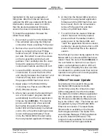
Figure 2. Microphone preamplifier gain 

configuration switches

Summary of Contents for M380

Page 1: ...ved www studio tech com 50625 0916 Issue 1 User Guide Issue 1 September 2016 This User Guide is applicable for serial numbers M380 00151 and later with application rmware 1 3 and later and Dante rmwar...

Page 2: ...This page intentionally left blank...

Page 3: ...uide Issue 1 September 2016 Studio Technologies Inc Page 3 Table of Contents Revision History 4 Introduction 5 Getting Started 8 Operation 14 Technical Notes 17 Speci cations 20 Appendix A Model 380 B...

Page 4: ...Issue 1 September 2016 Model 380 User Guide Page 4 Studio Technologies Inc Revision History Issue 1 September 2016 1 Initial release...

Page 5: ...ing microphone preampli er gain talk back button operation headphone signal routing and sidetone operation The Model 380 s audio quality is excellent with low distortion low noise and high headroom C...

Page 6: ...sired analog input such as the mic line input on an ENG style camera that s it The circuitry associated with the Model 380 s microphone output is very simple essentially a passive path that routes a s...

Page 7: ...ith a bit depth of up to 24 Channel routing headphone level control and sidetone creation are performed within the digital domain This provides exibil ity allows precise control and keeps the three le...

Page 8: ...3af Power over Ethernet PoE standard This allows fast and ef cient interconnection with the associated data network To support PoE power man agement the Model 380 s PoE interface reports to the power...

Page 9: ...wer There may be situations where the associated Ethernet switch does not pro vide PoE power In such cases an external PoE midspan power injector can be used If the selected midspan power injector is...

Page 10: ...ted to the microphone input Techni cally the output is identical to the signal that s connected to the microphone input but with a solid state muting circuit in series with the interconnection When th...

Page 11: ...he two Dante transmitter Tx channels associated with the Model 380 s Dante interface must be assigned to the desired receiver channels This achieves routing the Model 380 s two output audio chan nels...

Page 12: ...immediately be re ected in the unit s operation Accessing the Con guration Switches To access the ve con guration DIP switch es requires that the belt clip be rotated Normally the belt clip is secured...

Page 13: ...t headphone output channels In the monaural mode Dante channels 1 and 2 and sidetone audio are combined and sent to the left headphone output channel no signal is sent to the right headphone output Th...

Page 14: ...he talkback pushbutton switch will light in a quick test sequence to indicate that the main operating rmware embedded soft ware has started Once the sequence has completed and the Dante connection has...

Page 15: ...pend on how the headphone output has been con gured In the dual channel mode channel 1 audio will be sent to the left channel and channel 2 audio will be sent to the right channel Sidetone audio will...

Page 16: ...t When the talkback button is not pressed the button s green LED will be lit Latching If the talkback button has been con gured for the latching mode its operation is a bit different Momentarily press...

Page 17: ...e on the LAN Even two Dante enabled devices that are directly inter connected using an RJ45 patch cord will in most cases correctly acquire IP addresses and be able to com municate with each other An...

Page 18: ...le of what would be a typical rmware display if the talkback but ton s LED ashes green once followed by the LED ashing orange thrice it would indicate that application rmware version 1 3 is present in...

Page 19: ...ding process is over taking approximately 10 sec onds the Model 380 will restart using the newly loaded application rmware 6 At this time the Model 380 is function ing with the newly loaded applicatio...

Page 20: ...e main and talkback output channels Threshold 1 dB above nominal level 19 dBFS Slope 2 1 Status LED compressor active Microphone Output Type passive via 200 ohm resistors from micro phone input will p...

Page 21: ...uide Issue 1 September 2016 Studio Technologies Inc Page 21 Appendix A Model 380 Block Diagram The following block diagram shows a simpli ed version of the Model 380 s microphone input and microphone...

Reviews: