


External PSU for OnAir 2000
Date printed: 23.08.04
External PSU E5
2
WIRING AND HARDWARE INFORMATION
The optional external power supply unit for the OnAir 2000 console is
installed in a 19” 2U cabinet. If it is used, the standard internal power sup-
ply of the console is replaced by a connection unit with two 30-pin
Siemens connectors. Each of these allows connection to one external sup-
ply unit.
Usually, full redundancy is desired (order no. 1.942.109.00). In such a
case, two identical supply units are used. Their mains inlets should
preferably be connected to different phases of the mains. Each unit has its
own power switch and contains one (earlier versions: two) primary
switching power supply/ies and one secondary DC/DC converter. Each of
the external power supply units is connected with its own DC cable to the
console.
Pcs
Order no.
Designation
2
*
1.918.220/222*** Power Supply
2
1.918.225
Cable 2 m (longer cables on request)
Redundancy PSU Set
(1.942.109),
consisting of:
1
**
1.942.106
Connection Unit
2
89.20.2011
Power Supply Main (earlier versions)
or 1
89.20.2017
Power Supply Main (current versions)
1
1.942.105 ***
Power Supply
*
Power Supply (1.918.220 or 1.918.222***),
consisting of:
1
1.918.221
Sub Board PSU
1
1.942.107
Redundancy PSU Connection Board
**
Connection Unit (1.942.106),
consisting of:
Cables to DSP and Level Meter Interface
+ miscellaneous mounting hardware
***
Earlier versions only:
The Power Supply PCB 1.942.105.83 for
OnAir 2000M2 Modulo
devices requires an additional capacitor in paral-
lel with C11 and C16, due to the increased current drawn by the additional Remote Master and Slave PCBs. This capacitor is referenced
with “C*” in the diagram 1.942.105.83; it is mechanically mounted within the case (1.918.222) and hard-wired to the PCB.
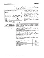
Front Panel LEDs
The external power supply unit has a red and four green LEDs on its front
panel; the four green LEDs indicate presence of the four supply voltages
(+15 V, –15 V, +5 V, and +24 V); the red “POWER ALARM” LED is on
if one of the DC supply voltages should fail. Should this happen, a power
alarm is triggered in addition.
Alarm Output
The power alarm output signal is sent to pin7A of the DC supply
connector. The power alarm output is a relay contact (40 V/200 mA max.).
Its behaviour depends on the setting of the jumper JS1 on the "Sub Board
for PSU" PCB.
Pin7A of the DC supply connector is normally floating, and pulled to GND
when power alarm is active (JP1 and JP2 connected with JS1, default
factory setting).
In the alternate jumper position (JP2 and JP3 connected with JS1), pin7A
is normally pulled to GND and becomes floating when alarm is active.
Note:
It is recommended to leave the jumper setting as it is. Should it be
changed, the POWER ALARM LED on the front panel of the supply unit
will be illuminated if everything is alright, and vice versa.
Alarm Indicator(s) in the Console
If required, power alarm indicator LEDs can be installed in a prominent
position within the console. For this purpose, connector P8 on the
Redundancy PSU Connection PCB has been provided. It allows to connect
Summary of Contents for OnAir 2000M2
Page 210: ......
Page 211: ......
Page 212: ......
Page 213: ......
Page 214: ......
Page 215: ......
Page 216: ......
Page 217: ......
Page 218: ......
Page 219: ......
Page 220: ......
Page 221: ......
Page 222: ......
Page 223: ......
Page 224: ......
Page 225: ......
Page 226: ......
Page 227: ......
Page 228: ......
Page 229: ......
Page 230: ......
Page 231: ......
Page 232: ......
Page 233: ......
Page 234: ......
Page 235: ......
Page 236: ......
Page 237: ......
Page 238: ......
Page 239: ......
Page 240: ......
Page 241: ......
Page 242: ......
Page 243: ......
Page 244: ......
Page 245: ......
Page 246: ......
Page 247: ......
Page 248: ......
Page 249: ......
Page 250: ......
Page 251: ......
Page 252: ......
Page 253: ......
Page 254: ......
Page 255: ......
Page 256: ......
Page 257: ......
Page 258: ......
Page 259: ......
Page 260: ......
Page 261: ......
Page 262: ......
Page 263: ......
Page 264: ......
Page 265: ......
Page 266: ......
Page 267: ......
Page 268: ......
Page 269: ......
Page 270: ......
Page 271: ......
Page 272: ......
Page 273: ......
Page 274: ......
Page 275: ......
Page 276: ......
Page 277: ......
Page 278: ......
Page 279: ......
Page 280: ......
Page 281: ......
Page 282: ......
Page 283: ......
Page 284: ......
Page 285: ......
Page 286: ......
Page 287: ......
Page 288: ......
Page 289: ......
Page 290: ......
Page 291: ......
Page 292: ......
Page 293: ......
Page 294: ......
Page 295: ......
Page 296: ......
Page 297: ......
Page 298: ......
Page 299: ...OnAir 2000 Digital Mixing Console Date printed 09 02 04 Section 1 Power Supply 1 942 105 84 0 ...
Page 300: ...OnAir 2000 Digital Mixing Console Date printed 09 02 04 Section 1 Power Supply 1 942 105 84 0 ...
Page 302: ......
Page 303: ......
Page 304: ......
Page 305: ......
Page 306: ......
Page 307: ......
Page 308: ......
Page 309: ......
Page 310: ......
Page 311: ......
Page 312: ......
Page 313: ......
Page 314: ......
Page 315: ......
Page 316: ......
Page 317: ......
Page 318: ......
Page 319: ......
Page 320: ......
Page 321: ......
Page 322: ......
Page 323: ......
Page 324: ......
Page 325: ......
Page 326: ......
Page 327: ......
Page 328: ......
Page 329: ......
Page 330: ......
Page 331: ......
Page 332: ......
Page 333: ......
Page 334: ......
Page 335: ......
Page 336: ......
Page 337: ......
Page 338: ......
Page 339: ......
Page 340: ......
Page 341: ......
Page 342: ......
Page 343: ......
Page 344: ......
Page 345: ......
Page 346: ......
Page 347: ......
Page 348: ......
Page 349: ......
Page 350: ......
Page 351: ......
Page 352: ......
Page 353: ......
Page 354: ......
Page 355: ......
Page 356: ......
Page 357: ......
Page 358: ......
Page 359: ......
Page 360: ......
Page 361: ......
Page 362: ......
Page 363: ......
Page 364: ......
Page 365: ......
Page 366: ......
Page 367: ......
Page 368: ......
Page 369: ......
Page 371: ......
Page 372: ......
Page 373: ......
Page 374: ......
Page 375: ......
Page 376: ......
Page 377: ......
Page 378: ......
Page 379: ......
Page 380: ......
Page 381: ......
Page 382: ......
Page 383: ......
Page 384: ......
Page 385: ......
Page 386: ......
Page 387: ......
Page 388: ......
Page 389: ......
Page 390: ......
Page 391: ......
Page 392: ......
Page 393: ......
Page 394: ......
Page 395: ......
Page 396: ......
Page 397: ......
Page 398: ......
Page 399: ......
Page 400: ......
Page 401: ......
Page 402: ......
Page 403: ......
Page 404: ......
Page 405: ......
Page 406: ......
Page 407: ......
Page 408: ......
Page 409: ......
Page 410: ......
Page 411: ......
Page 413: ......
Page 414: ......
Page 415: ......
Page 416: ......
Page 417: ......
Page 418: ......
Page 419: ......
Page 420: ......
Page 421: ......
Page 422: ......
Page 423: ......
Page 424: ......
Page 425: ......
Page 426: ......
Page 427: ...External Supply Unit for Studer OnAir 2000 Mixing Console Operating and Service Instructions ...
Page 435: ......
Page 436: ......
Page 437: ......
Page 438: ......
Page 439: ......
Page 440: ......
Page 441: ...OnAir 2000 Digital Mixing Console Date printed 23 08 04 Power Supply 1 942 105 84 0 ...
Page 442: ...OnAir 2000 Digital Mixing Console Date printed 23 08 04 Power Supply 1 942 105 84 0 ...
Page 444: ......
Page 445: ......
Page 446: ......
Page 447: ......
Page 448: ......
Page 449: ......


